Toyota RAV4 (XA40) 2013-2018 Service Manual: Evaporative emission control system leak detected
Dtc summary
Description
The description can be found in the evap (evaporative emission) system (see page es-335).
Inspection procedure
Refer to the evap system (see page es-340).
Monitor description
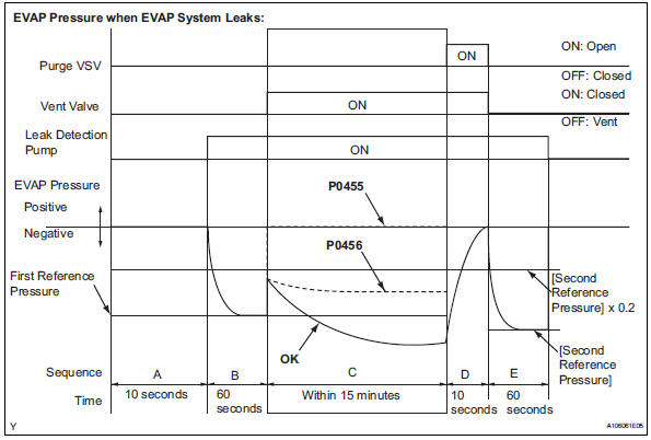
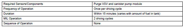
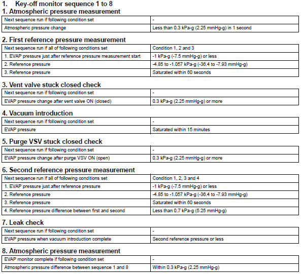
5 Hours* after the ignition switch is turned off, the leak detection pump creates negative pressure (vacuum) in the evap system. The ecm monitors for leaks and actuator malfunctions based on the evap pressure.
Hint:
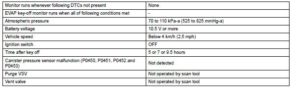
*: If the engine coolant temperature is not below 35°c (95°f) 5 hours after the ignition switch is turned off, the monitor check starts 2 hours later. If it is still not below 35°c (95°f) 7 hours after the ignition switch is turned off, the monitor check starts 2.5 Hours later.
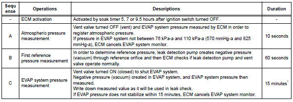
*: If only a small amount of fuel is in the fuel tank, it takes longer for the evap pressure to stabilize.
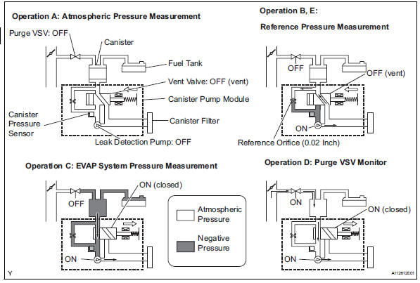
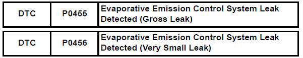
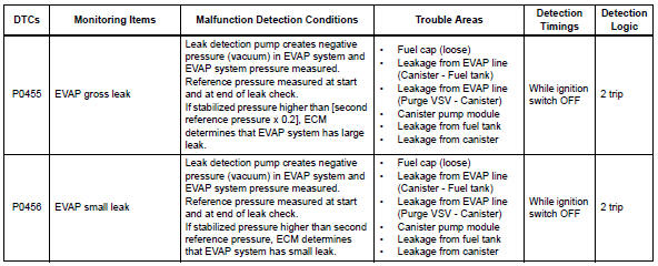
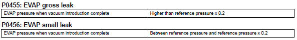
- P0455: evap gross leak
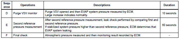
In operation c, the leak detection pump creates negative pressure (vacuum) in the evap system and the evap system pressure is measured. If the stabilized system pressure is higher than [second reference pressure x 0.2] (Near atmospheric pressure), the ecm determines that the evap system has a large leakage, illuminates the mil and sets the dtc (2 trip detection logic).
- P0456: evap very small leak
In operation c, the leak detection pump creates negative pressure (vacuum) in the evap system and the evap system pressure is measured. If the stabilized system pressure is higher than the second reference pressure, the ecm determines that the evap system has a small leakage, illuminates the mil and sets the dtc (2 trip detection logic).
Monitor strategy
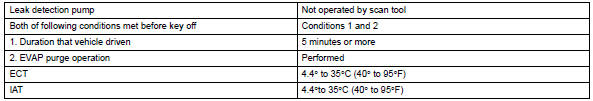
Typical enabling conditions
Typical malfunction thresholds
Monitor result
Refer to checking monitor status (see page es-17).
 Evaporative emission control system pressure sensor
Dtc summary
Hint:
The canister pressure sensor is built into the canister pump module.
Description
The description can be found in the evap (evaporative emission) system (see
page es ...
 Vehicle speed sensor "A"
description
The speed sensor detects the wheel speed and sends the appropriate signals to
the skid control ecu.
The skid control ecu converts these wheel speed signals into a 4-pulse signal ...
Other materials:
Center airbag sensor communication stop mode
Description
Wiring diagram
Inspection procedure
Notice:
Turn the ignition switch off before measuring the resistances of the
main wire and the branch
wire.
After the ignition switch is turned off, check that the key reminder
warning system and light
reminder warning system ...
Windshield wipers and
washer
Operating the lever can
switch between automatic
operation and manual operation,
or can use the
washer.
NOTICE
â– When the windshield is dry
Do not use the wipers, as they
may damage the windshield.
Operating the wiper lever
Operating the lever operates
the wipers or washer as follows:
Intermittent ...
Front seat assembly (for manual seat)
Components
...
