Toyota RAV4 (XA40) 2013-2018 Service Manual: Engine coolant temperature circuit
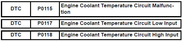
Description
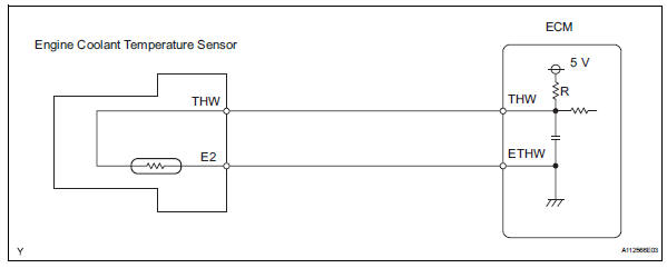
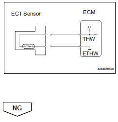
A thermistor, whose resistance value varies according to the ect, is built into the engine coolant temperature (ect) sensor.
The structure of the sensor and its connection to the ecm are the same as those of the intake air temperature (iat) sensor.
Hint:
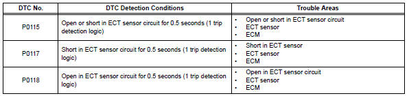
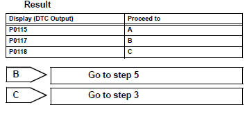
When any of dtcs p0115, p0117 and p0118 are set, the ecm enters fail-safe mode. During fail-safe mode, the ect is estimated to be 80°c (176°f) by the ecm. Fail-safe mode continues until a pass condition is detected.
Hint:
When any of these dtcs are set, check the ect by selecting the following menu items on the intelligent tester: diagnosis / enhanced obd ii / data list / primary / coolant temp.

Monitor description
The engine coolant temperature (ect) sensor is used to monitor the ect. The ect sensor has a thermistor with a resistance that varies according to the temperature of the engine coolant. When the coolant temperature is low, the resistance in the thermistor increases. When the temperature is high, the resistance drops. These variations in resistance are reflected in the output voltage from the sensor. The ecm monitors the sensor voltage and uses this value to calculate the ect. When the sensor output voltage deviates from the normal operating range, the ecm interprets this as a fault in the ect sensor and sets a dtc.
Example: if the sensor output voltage is more than 4.91 V for 0.5 Seconds or more, the ecm determines that there is an open in the ect sensor circuit, and sets dtc p0118. Conversely, if the voltage output is less than 0.14 V for 0.5 Seconds or more, the ecm determines that there is a short in the sensor circuit, and sets dtc p0117.
If the malfunction is not repaired successfully, a dtc is set 0.5 Seconds after the engine is next started.
Monitor strategy
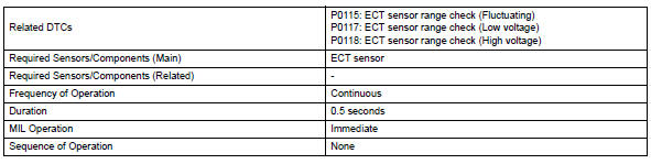
Typical enabling conditions
![]()
Typical malfunction thresholds
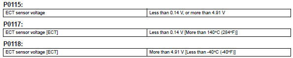
Component operating range
![]()
Wiring diagram
Inspection procedure
Hint:
Read freeze frame data using the intelligent tester. Freeze frame data records the engine condition when malfunctions are detected. When troubleshooting, freeze frame data can help determine if the vehicle was moving or stationary, if the engine was warmed up or not, if the air-fuel ratio was lean or rich, and other data, from the time the malfunction occurred.
- Read output dtc
- Connect the intelligent tester to the dlc3.
- Turn the ignition switch on and turn the intelligent tester on.
- Select the following menu items: diagnosis / enhanced obd ii / dtc info / current codes.
- Read dtcs.

- Read value using intelligent tester (engine coolant temperature)
- Connect the intelligent tester to the dlc3.
- Turn the ignition switch on.
- Turn the tester on.
- Select the following menu items: diagnosis / enhanced obd ii / data list / primary / coolant temp.
- Read the value displayed on the tester.
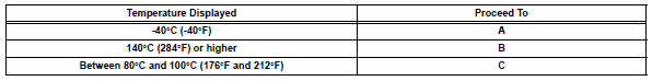
Standard value: between 80°c and 100°c (167°f and 212°f) with warm engine.
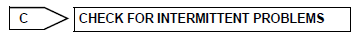
Result
Hint:
- If there is an open circuit, the intelligent tester indicates -40°c (-40°f).
- If there is a short circuit, the intelligent tester indicates
140°c (284°f) or higher.


- Read value using intelligent tester (check for open in wire harness)
- Disconnect the b4 engine coolant temperature (ect) sensor connector.
- Connect terminals 1 and 2 of the ect sensor connector on the wire harness side.
- Connect the intelligent tester to the dlc3.
- Turn the ignition switch on.
- Turn the tester on.
- Select the following menu items: diagnosis / enhanced obd ii / data list / primary / coolant temp.
- Read the value displayed on the tester.
Standard value: 140°c (284°f) or higher.
- Reconnect the ect sensor connector.
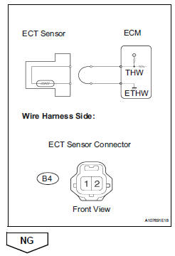
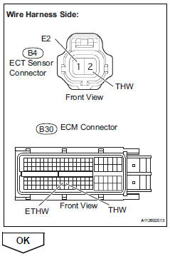
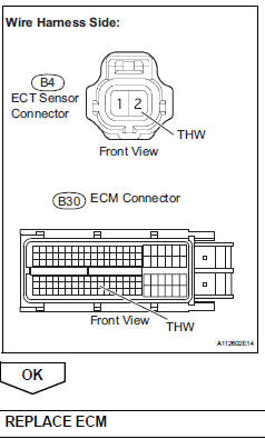
- Check harness and connector (engine coolant temperature sensor - ecm)
- Disconnect the b4 ect sensor connector.
- Disconnect the b30 ecm connector.
- Measure the resistance.
Standard resistance 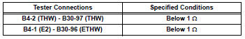
- Reconnect the ect sensor connector.
- Reconnect the ecm connector.
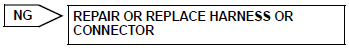
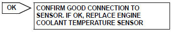
Good connection to ecm. If ok, replace ecm
- Read value using intelligent tester (check for short in wire harness)
- Disconnect the b4 ect sensor connector.
- Connect the intelligent tester to the dlc3.
- Turn the ignition switch on.
- Turn the tester on.
- Select the following menu items: diagnosis / enhanced obd ii / data list / primary / coolant temp.
- Read the value displayed on the tester.
Standard value: -40°c (-40°f)
- Reconnect the ect sensor connector.
- Check harness and connector (engine coolant temperature sensor - ecm)
- Disconnect the b4 ect sensor connector.
- Disconnect the b30 ecm connector.
- Measure the resistance.
Standard resistance 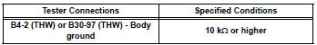
- Reconnect the ect sensor connector.
- Reconnect the ecm connector.
 Intake air temperature sensor gradient too high
Description
The intake air temperature (iat) sensor, mounted on the mass air flow (maf)
meter, monitors the iat.
The iat sensor has a built-in thermistor with a resistance that varies ac ...
 Engine coolant temperature circuit range / performance problem
Description
Refer to dtc p0115 (see page es-105).
Monitor description
Engine coolant temperature (ect) sensor cold start monitor
When a cold engine start is performed and then the engine i ...
Other materials:
Circuit opening relay
On-vehicle inspection
Disconnect cable from negative battery
terminal
Caution:
Wait at least 90 seconds after disconnecting the
cable from the negative (-) battery terminal to
prevent airbag and seat belt pretensioner activation.
Inspect instrument panel junction block
Notice:
Th ...
Removal
Disconnect cable from negative battery
terminal
Caution:
Wait at least 90 seconds after disconnecting the
cable from the negative (-) battery terminal to
prevent airbag and seat belt pretensioner activation.
Remove no. 1 Engine cover (see page es-410)
Remove air cleaner cap (see pag ...
On-vehicle inspection
Check throttle body
Check the throttle control motor operating sounds.
Turn the ignition switch on.
When pressing the accelerator pedal, check
the operating sound of the running motor. Make
sure that no friction noises emit from the motor.
If friction noise exists, replace t ...
