Toyota RAV4 (XA40) 2013-2018 Service Manual: Intake air temperature circuit malfunction
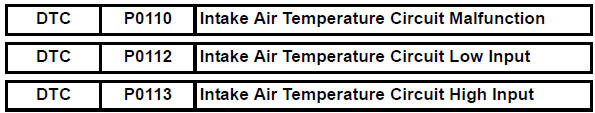
Description
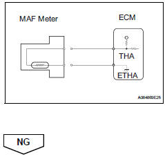
The intake air temperature (iat) sensor, mounted on the mass air flow (maf) meter, monitors the iat.
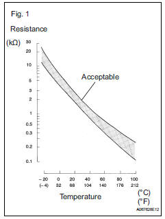
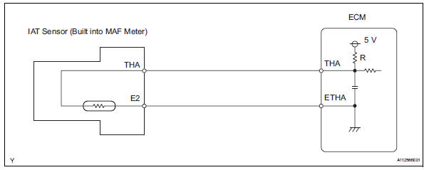
The iat sensor has a built-in thermistor with a resistance that varies according to the temperature of the intake air. When the iat is low, the resistance of the thermistor increases. When the temperature is high, the resistance drops. These variations in resistance are transmitted to the ecm as voltage changes (see fig. 1).
The iat sensor is powered by a 5 v supply from the tha terminal of the ecm, via resistor r.
Resistor r and the iat sensor are connected in series. When the resistance value of the iat sensor changes, according to changes in the iat, the voltage at terminal tha also varies. Based on this signal, the ecm increases the fuel injection volume when the engine is cold to improve drivability.
Hint: when any of dtcs p0110, p0112 and p0113 are set, the ecm enters fail-safe mode. During fail-safe mode, the iat is estimated to be 20°c (68°f) by the ecm. Fail-safe mode continues until a pass condition is detected.
Hint:
When any of these dtcs are set, check the iat by selecting the following menu items on the intelligent tester: diagnosis / enhanced obd ii / data list / primary / intake air.

Monitor description
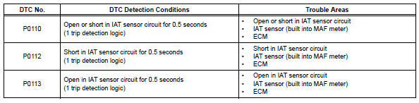
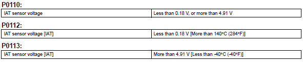
The ecm monitors the sensor voltage and uses this value to calculate the iat. When the sensor output voltage deviates from the normal operating range, the ecm interprets this as a malfunction in the iat sensor and sets a dtc.
Example: if the sensor output voltage is more than 4.91 V for 0.5 Seconds or more, the ecm determines that there is an open in the iat sensor circuit, and sets dtc p0113. Conversely, if the output voltage is less than 0.18 V for 0.5 Seconds or more, the ecm determines that there is a short in the sensor circuit, and sets dtc p0112.
If the malfunction is not repaired successfully, a dtc is set 0.5 Seconds after the engine is next started.
Monitor strategy
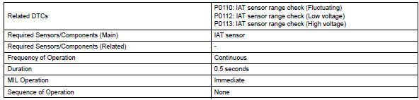
Typical enabling conditions
![]()
Typical malfunction thresholds
Component operating range
![]()
Wiring diagram
Inspection procedure
Hint:
Read freeze frame data using the intelligent tester. Freeze frame data records the engine condition when malfunctions are detected. When troubleshooting, freeze frame data can help determine if the vehicle was moving or stationary, if the engine was warmed up or not, if the air-fuel ratio was lean or rich, and other data from the time the malfunction occurred.
- Read output dtc
- Connect the intelligent tester to the dlc3.
- Turn the ignition switch on and turn the intelligent tester on.
- Select the following menu items: diagnosis / enhanced obd ii / dtc info / current codes.
- Read dtcs.
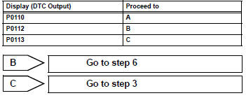
Result

- Read value using intelligent tester (intake air temperature)
- Connect the intelligent tester to the dlc3.
- Turn the ignition switch on.
- Turn the tester on.
- Select the following menu items: diagnosis / enhanced obd ii / data list / primary / intake air.
- Read the value displayed on the tester.
Standard: same as actual intake air temperature (iat).
Result 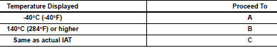
Hint:
- If there is an open circuit, the intelligent tester indicates -40°c (-40°f).
- If there is a short circuit, the intelligent tester indicates 140°c (284°f) or higher.

- Read value using intelligent tester (check for open in wire harness)
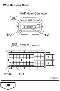
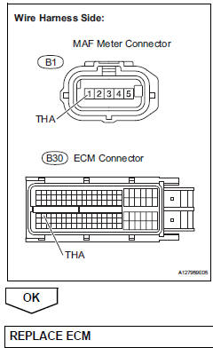
- Disconnect the b1 mass air flow (maf) meter connector.
- Connect terminals tha and e2 of the maf meter wire harness side connector.
- Connect the intelligent tester to the dlc3.
- Turn the ignition switch on.
- Turn the tester on.
- Select the following menu items: diagnosis / enhanced obd ii / data list / primary / intake air.
- Read the value displayed on the tester.
Standard value: 140°c (284°f) or higher
- Reconnect the maf meter connector.
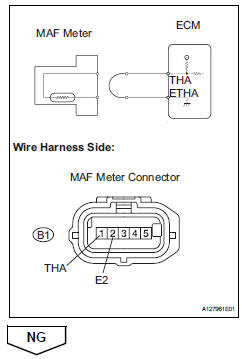
- Check harness and connector (mass air flow meter - ecm)
- Disconnect the b1 maf meter connector.
- Disconnect the b30 ecm connector.
- Measure the resistance.
Standard resistance 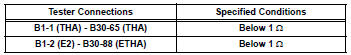
- Reconnect the maf meter connector.
- Reconnect the ecm connector.
Confirm good connection to ecm. If ok, replace ecm
- Read value using intelligent tester (check for short in wire harness)
- Disconnect the b1 maf meter connector.
- Connect the intelligent tester to the dlc3.
- Turn the ignition switch on.
- Turn the tester on.
- Select the following menu items: diagnosis / enhanced obd ii / data list / primary / intake air.
- Read the value displayed on the tester.
Standard value: -40°c (-40°f)
- Reconnect the maf meter connector.

- Check harness and connector (mass air flow meter - ecm)
- Disconnect the b1 maf meter connector.
- Disconnect the b30 ecm connector.
- Measure the resistance.
Standard resistance 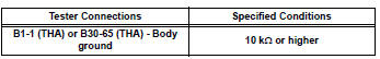
- Reconnect the maf meter connector.
- Reconnect the ecm connector.

 Mass air flow circuit range / performance problem
Description
Refer to dtc p0100 (see page es-86).
Monitor description
The maf meter is a sensor that measures the amount of air flowing through the
throttle valve. The ecm
uses this infor ...
 Intake air temperature sensor gradient too high
Description
The intake air temperature (iat) sensor, mounted on the mass air flow (maf)
meter, monitors the iat.
The iat sensor has a built-in thermistor with a resistance that varies ac ...
Other materials:
Using the radio
Power
Volume
Adjusting the frequency
Scanning for receivable stations
Am/fm mode button
Station selectors
Seeking the frequency
Displaying text message
Setting station presets
Search for the desired stations by turning the ¢Â§tune¢escroll¢¸
knob or ...
Installation
Install throttle body
Install a new gasket onto the intake manifold.
Install the throttle body and fuel pipe clamp with the
4 bolts.
Torque: 30 n*m (305 kgf*cm, 22 ft.*Lbf)
Connect the fuel tube into the clamp.
Connect the wire harness clamp.
Connect the throttle posi ...
Air conditioning filter
The air conditioning filter must be changed regularly to maintain
air conditioning efficiency.
Removal method
Vehicles without a smart key system: turn the engine switch to the
“lock” position.
Vehicles with a smart key system: turn the engine switch off.
Open the glove box. Slide ...
