Toyota RAV4 (XA40) 2013-2018 Service Manual: Compressor solenoid circuit (2006/01- )

Description
In this circuit, the compressor receives a refrigerant compression demand signal from the air conditioning amplifier. Based on this signal, the compressor changes the degree of refrigerant compression.
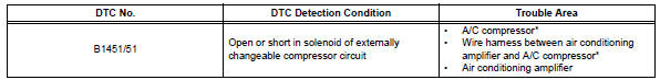
Hint:
*: Compressor and pulley for 2az-fe, compressor and magnetic clutch for 2gr-fe
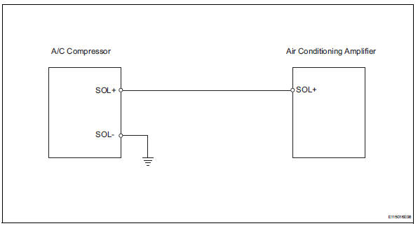
Wiring diagram
Inspection procedure
- Read value of intelligent tester (reg ctrl currnt)
- Connect the intelligent tester (with can vim) to the dlc3.
- Turn the ignition switch on and turn the intelligent tester main switch on.
- Select the items below in the data list, and read the value displayed on the intelligent tester.
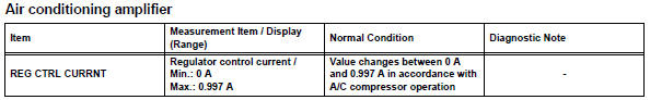
Ok: the display is as specified in the normal condition column.
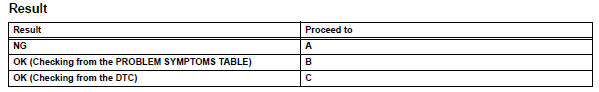

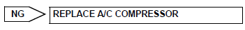
- Inspect a/c compressor
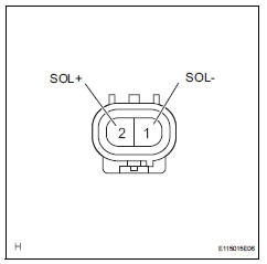
- Disconnect the a/c compressor connector.
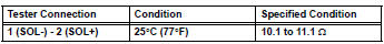
- Measure the resistance of the connector.
Standard resistance

- Check wire harness (a/c compressor - air conditioning amplifier)
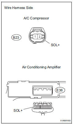
- Disconnect the b23 a/c compressor connector.
- Disconnect the e36 amplifier connector.
- Measure the resistance of the wire harness side connectors.
Standard resistance 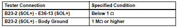

- Check wire harness (a/c compressor - body ground)
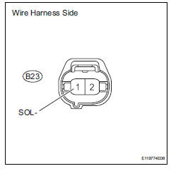
- Disconnect the b23 a/c compressor connector.
- Measure the resistance of the wire harness side connector.
Standard resistance 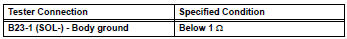


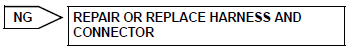
Replace air conditioning amplifier
 Compressor solenoid circuit (2005/11-2006/01)
Description
In this circuit, the compressor receives a refrigerant compression demand
signal from the air conditioning
amplifier. Based on this signal, the compressor changes the degree of
r ...
 Multiplex communication circuit
Description
The air conditioning amplifier communicates data with the ecm and combination
meter through the can
communication system.
Wiring diagram
Inspection procedure
Check dt ...
Other materials:
Vehicle load limits
Vehicle load limits include total load capacity, seating capacity,
twr (trailer weight rating) and cargo capacity.
Total load capacity (vehicle capacity weight)
Total load capacity means the combined weight of occupants, cargo
and luggage.
Seating capacity: 5 occupants (front 2, rear 3)
Seatin ...
Daytime running light relay
On-vehicle inspection
Inspect day time running light relay
Remove the no. 2 Relay, no. 3 Relay and no. 4 Relay
from the engine room no. 2 Relay block.
Measure the resistance of the relays.
Standard resistance:
No. 2, No. 4
No. 3
If the result is not as specified, replace th ...
Data list / active test
Active test
Hint:
Performing the intelligent tester active test allows
relay, vsv, actuator and other items to be operated
without removing any parts. Performing the active
test early in troubleshooting is one way to save time.
The data list can be displayed during the active
test.
...
