Toyota RAV4 (XA40) 2013-2018 Service Manual: Front stabilizer bar
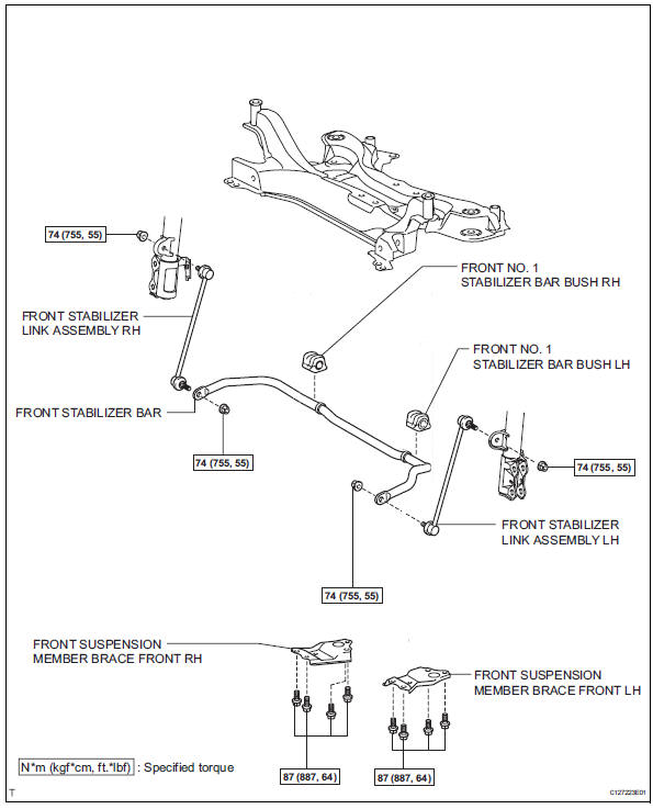
Components
Removal
- Remove front wheel
- Remove front stabilizer link assembly lh
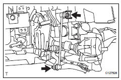
- Remove the 2 nuts and stabilizer link.
- Remove front stabilizer link assembly rh
Hint:
Use the same procedures described for the lh side.
- Remove front suspension member brace front lh
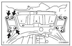
- Remove the 4 bolts and member brace from the corssmember.
- Remove front suspension member brace front rh
Hint:
Use the same procedures described for the lh side.
- Remove front stabilizer bar
- Remove the stabilizer bar from the crossmember.
- Remove front no. 1 Stabilizer bar bush lh
- Remove the bush from the stabilizer bar.
- Remove front no. 1 Stabilizer bar bush rh
Hint
Use the same procedures described for the lh side.
Inspection
- Inspect front stabilizer link assembly lh
- As shown in the illustration, move the ball joint stud back and forth 5 times before installing the nut.
- Using a torque wrench, turn the nut continuously at a rate of 3 to 5 seconds per turn and take the torque reading on the fifth turn.
Turning torque: 0.05 To 1.96 N*m, (0.5 To 20 kgf*cm, 0.4 To 17 in.*Lbf) or less
- Check for any cracks and grease leaks on the ball joint dust cover.
Installation
- Install front no. 1 Stabilizer bar bush lh
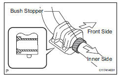
- Install the bush.
Hint:
- Install each bush to the inner side of each bush stopper on the stabilizer bar.
- Install each bush with its slit facing the vehicle rear side.
- Remove front no. 1 Stabilizer bar bush rh
Hint:
Use the same procedures described for the lh side.
- Install front stabilizer bar
- Install the stabilizer bar to the crossmember.
- Install front suspension member brace front lh
- Install the member brace with the 4 bolt to the suspension member.
Torque: 87 n*m (887 kgf*cm, 64 ft.*Lbf)
- Install front suspension member brace front rh
Hint:
Use the same procedures described for the lh side.
- Install front stabilizer link assembly lh
- Install the link with the 2 nut.
Torque: 74 n*m (755 kgf*cm, 55 ft.*Lbf)
- Install front stabilizer link assembly rh
Hint:
Use the same procedures described for the lh side.
- Install front wheel torque: 103 n*m (1,050 kgf*cm, 76 ft.*Lbf)
- Stabilize suspension (see page sp-12)
 Front lower ball joint
Components
Removal
Hint:
Use the same procedures for the rh side and lh side.
The procedures listed below are for the lh side.
Remove front wheel
Remove front speed sensor lh (for ...
 Rear coil spring
Components
Removal
Hint:
Use the same procedures for the rh side and lh side.
The procedures listed below are for the lh side.
Remove rear wheel
Remove skid control sensor wire (fo ...
Other materials:
Components
(2006/01- )
...
Condenser
Components
On-vehicle inspection
Inspect cooler condenser assembly
If the fins of the cooler condenser are dirty, clean
them with water. Dry the fins with compressed air.
Notice:
Do not damage the fins of the condenser.
If a fin of the cooler condenser is bent, straighte ...
Headlight (hi-beam) circuit
Description
The body ecu controls the headlight relay, no. 2 Daytime running light relay
(marking: drl no. 2) And
no. 4 Daytime running light relay (marking: drl no. 4).
Wiring diagram
Inspection procedure
Perform active test by intelligent tester
Connect the intelligent test ...
