Toyota RAV4 (XA40) 2013-2018 Service Manual: Ig power source circuit
Description
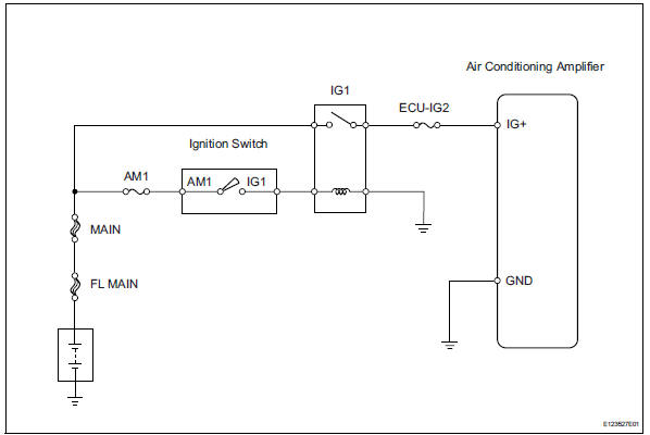
This is the main power source supplied to the air conditioning amplifier when the ignition switch is on (ig). This power source is used for operating components, such as the air conditioning amplifier and servo motors.
Wiring diagram
Inspection procedure
- Inspect fuse (ecu-ig2)
- Remove the ecu-ig2 fuse from the instrument panel junction block.
- Measure the resistance of the fuse.
Standard resistance:
below 1 


- Check wire harness (air conditioning amplifier - battery)
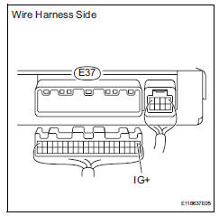
- Disconnect the e37 amplifier connector.
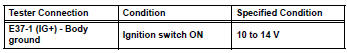
- Measure the voltage of the wire harness side connector.
Standard voltage

- Check wire harness (air conditioning amplifier - body ground)
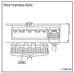
- Disconnect the e37 amplifier connector.
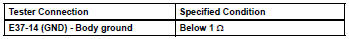
- Measure the resistance of the wire harness side connector.
Standard resistance

Proceed to next circuit inspection shown in problem symptoms table
 Compressor circuit
Description
When the a/c switch is turned on, the magnetic clutch on signal is sent from
the air conditioning
amplifier. Then the mg clt relay turns on to operate the magnetic clutch.
Wiring diag ...
 Back-up power source circuit
Description
This is the back-up power source circuit for the air conditioning amplifier.
Power is supplied even when the
ignition switch is turned off and is used for functions such as the diagnos ...
Other materials:
Functions included in
LTA system
â– Lane departure alert function
When the system determines that the vehicle might depart
from its lane or course*, a warning
is displayed on the multi-information
display, and a warning
buzzer will sound to alert the
driver.
When the warning buzzer sounds,
check the area around your vehicle
and c ...
Blower resistor
On-vehicle inspection
Inspect blower motor control
Measure the resistance of the blower resistor.
Standard resistance
If the resistance is not as specified, replace the
blower motor control. ...
Hood
Release the lock from the inside of the vehicle to open the hood
Pull the hood lock release lever.
The hood will pop up slightly.
Push the auxiliary catch lever to
the left and lift the hood.
Hold the hood open by inserting
the supporting rod into the slot.
Cautio ...
