
Toyota RAV4 (XA40) 2013-2018 Service Manual: Back-up power source circuit
Description
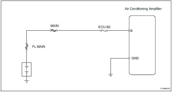
This is the back-up power source circuit for the air conditioning amplifier. Power is supplied even when the ignition switch is turned off and is used for functions such as the diagnostic trouble code memory.
wiring diagram
Inspection procedure
- Inspect fuse (ecu-b2)
- Remove the ecu-b2 fuse from the engine room no. 2 Relay block.
- Measure the resistance of the fuse.
Standard resistance:
below 1 


- Check wire harness (air conditioning amplifier - battery)
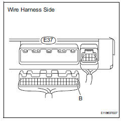
- Disconnect the e37 amplifier connector.
- Measure the voltage of the wire harness side connector.
Standard voltage



- Check wire harness (air conditioning amplifier - body ground)
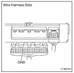
- Disconnect the e37 amplifier connector.
- Measure the resistance of the wire harness side connector.
Standard resistance



Proceed to next circuit inspection shown in problem symptoms table
 Ig power source circuit
Description
This is the main power source supplied to the air conditioning amplifier when
the ignition switch is on
(ig). This power source is used for operating components, such as the air
cond ...

Other materials:
Installation
Install fan and generator v belt
Using sst and 19 mm socket wrench, loosen the vribbed
belt tensioner arm clockwise, then install the
fan and generator v belt.
Sst 09216-42010
Notice:
Be sure to connect sst and the tools so that
they are in line during use.
When retracti ...
Tire pressure warning valve and transmitter
Components
Removal
Remove front tire
Remove rear tire
Remove tire pressure warning valve subassembly
Remove the valve core and cap, and release air
from the tire.
After ensuring that air is sufficiently released,
remove the nut and washer that are used to fix the
tire pres ...
Idle control system malfunction
Description
The idling speed is controlled by the etcs (electronic throttle control
system). The etcs is comprised
of: 1) the one valve type throttle body; 2) the throttle actuator, which
operates the throttle valve; 3) the
throttle position (tp) sensor, which detects the opening angle of ...
