Toyota RAV4 (XA40) 2013-2018 Service Manual: Rear coil spring
Components
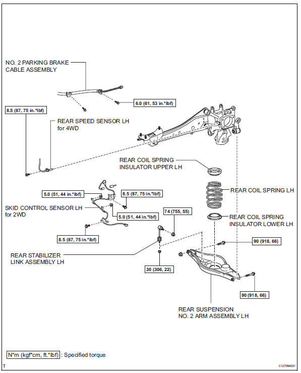
Removal
Hint:
- Use the same procedures for the rh side and lh side.
- The procedures listed below are for the lh side.
- Remove rear wheel
- Remove skid control sensor wire (for 2wd) (see page bc-198)
- Remove rear speed sensor lh (for 4wd) (see page bc-205)
- Disconnect no. 2 Parking brake cable assembly (see page pb-8)
- Disconnect rear stabilizer link assembly lh (see page sp-50)
- Disconnect rear suspension no. 2 Arm subassembly lh
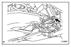
- Loosen the bolt from the suspension member side.
Notice:
Do not remove the bolt and nut. Only loosen them.
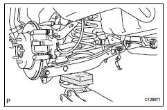
- Support the no. 2 Suspension arm lh with a jack.
Notice:
Place a wooden or rubber block between the jack and arm.
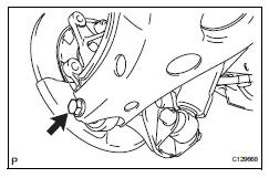
- Remove the bolt and nut from the axle carrier side.
- Slowly lower the jack, and disconnect the no. 2 Suspension arm from the axle carrier.
- Remove rear coil spring insulator upper lh
- Remove the insulator upper from the coil spring.
- Remove rear coil spring lh
- Remove the coil spring from the suspension no. 2 Arm
- Remove rear coil spring insulator lower lh
- Remove the insulator lower from the suspension no. 2 Arm.
Installation
Hint:
- Use the same procedures for the rh side and lh side.
- The procedures listed below are for the lh side.
- Install rear coil spring insulator lower lh
- Install the insulator lower to the suspension no. 2 Arm.
- Remove rear coil spring lh
- Install the coil spring to the suspension no. 2 Arm.
- Install rear coil spring insulator upper lh
- Align the stopper part of the insulator upper with the coil spring tip, and install the insulator upper.
- Temporarily install rear suspension no. 2 Arm assembly lh
- Slowly raise the suspension no. 2 Arm with a jack, and connect the suspension no. 2 Arm to the axle carrier.
- Install the bolt and nut.
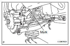
Notice:
Install the arm so that the coil spring's distinguishing mark is on the outer side of the vehicle.
- Install rear stabilizer link assembly lh (see page sp-50)
- Connect no. 2 Parking brake cable assembly (see page pb-9)
- Install skid control sensor wire (for 2wd) (see page bc-201)
- Install rear speed sensor lh (for 4wd) (see page bc-206)
- Install rear wheel torque: 103 n*m (1,050 kgf*cm, 76 ft.*Lbf)
- Stabilize suspension (see page sp-37)
- Tighten rear suspension no. 2 Arm assembly lh (see page sp-46)
- Check speed sensor signal
- Check the speed sensor signal (see page bc-44).
- Inspect and adjust rear wheel alignment
- Inspect and adjust the rear wheel alignment (see page sp-7).
 Front stabilizer bar
Components
Removal
Remove front wheel
Remove front stabilizer link assembly lh
Remove the 2 nuts and stabilizer link.
Remove front stabilizer link assembly rh
Hint:
Use ...
 Rear shock absorber
Components
Removal
Hint
Use the same procedures for the rh side and lh side.
The procedures listed below are for the lh side.
Remove rear wheel
Remove rear shock absorber assembly ...
Other materials:
Headlight dimmer switch
Precaution
Precaution for vehicle with srs
Some procedures in this section may affect the
supplemental restraint system (srs). Prior to
performing the procedures, read the srs section's
"precaution" (see page rs-1).
Components
Removal
Disconnect cable from negat ...
Data list / active test
Read data list
Hint:
Using the intelligent tester's data list allows switch,
actuator and other item values to be read without
removing any parts. Reading the data list early in
troubleshooting is one way to save time.
Connect the intelligent tester (with can vim) to the
dlc3.
Turn ...
Weight limits
The gross trailer weight must
never exceed the TWR
described below.
Without towing package
1500 lb. (680 kg)
With towing package
3500 lb. (1590 kg)
The gross combination weight
must never exceed the
GCWR described below.
Without towing package
Vehicles without Dynamic Torque
Vectoring AWD ...
