Toyota RAV4 (XA40) 2013-2018 Service Manual: Rear shock absorber
Components
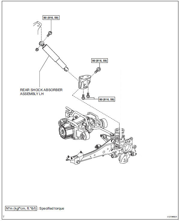
Removal
Hint
- Use the same procedures for the rh side and lh side.
- The procedures listed below are for the lh side.
- Remove rear wheel
- Remove rear shock absorber assembly lh
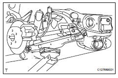
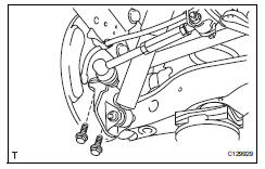
- Support the no. 2 Suspension arm lh with a jack.
Notice:
Place a wooden or rubber block between the jack and arm.
- Remove the bolt and 2 nuts from the suspension member and axle carrier.
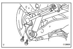
- Remove the 2 bolts and disconnect the shock absorber with the bracket.
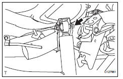
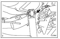
- Remove the nut and bolt from the shock absorber upper side.
- Remove the shock absorber from the vehicle.
- Remove the nut and bolt from the bracket.
Hint:
While fixing the nut in place, loosen and remove the bolt.
Inspection
- Inspect rear shock absorber assembly lh
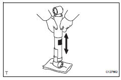
- Compress and extend the shock absorber rod, and
check that there is no abnormal resistance or
unusual sound during operation.
If there is any abnormality, replace the shock absorber with a new one.
Notice:
When disposing of the shock absorber, see disposal (see page sp-37).
Installation
Hint:
- Use the same procedures for the rh side and lh side.
- The procedures listed below are for the lh side.
- Temporarily install rear shock absorber assembly lh
- Temporarily install the bracket to the shock absorber with the bolt and nut.
Notice:
Fix the nut in place and temporarily install the bolt.
- Temporarily install the shock absorber upper side to the suspension member with the bolt and nut.
Notice:
Fix the nut in place and temporarily install the bolt.
- Install the shock absorber with the 2 bolts to the axle carrier.
Torque: 80 n*m (816 kgf*cm, 59 ft.*Lbf)
- Temporarily install the suspension arm with the bolt and 2 nuts to the suspension member and axle carrier.
- Temporarily install rear upper control arm assembly lh (see page sp-40)
- Install rear wheel torque: 103 n*m (1,050 kgf*cm, 76 ft.*Lbf)
- Stabilize suspension
- Lower the vehicle.
- Press down on the vehicle several times to stabilize the suspension.
- Tighten rear shock absorber assembly lh
- Fix the nut in place and tighten the bolt.
Torque: 80 n*m (816 kgf*cm, 59 ft.*Lbf)
- Inspect and adjust rear wheel alignment
- Inspect and adjust the rear wheel alignment (see page sp-7).
Disposal
- Dispose of rear shock absorber assembly lh
- Fully extend the shock absorber rod, and clamp it in a vise at an angle.
- Using a drill, make a hole near the center of the cylinder in the hatched area shown in the illustration to discharge the gas inside.
Caution:
As metal debris may be blown outward by the gas, you must:
- Wear protective glasses.
- Cover the area being cut.
Notice:
The gas is colorless, odorless and harmless
 Rear coil spring
Components
Removal
Hint:
Use the same procedures for the rh side and lh side.
The procedures listed below are for the lh side.
Remove rear wheel
Remove skid control sensor wire (fo ...
 Rear upper control arm
Components
Removal
Hint:
Use the same procedures for the rh side and lh side.
The procedures listed below are for the lh side.
Remove rear wheel
Disconnect skid control sensor wire ...
Other materials:
Valve clearance
Adjustment
Disconnect cable from negative battery
terminal
Caution:
Wait at least 90 seconds after disconnecting the
cable from the negative (-) battery terminal to
prevent airbag and seat belt pretensioner activation.
Remove front wheel rh
Remove no. 1 Engine under cover
Remove ...
Operation check
Illuminated entry system operation check
The illuminated entry system controls the following
lights:
Ignition key cylinder light*1 or transponder key
amplifier*2
Foot light
Map light and room light
Hint:
*1: W/o engine immobiliser system
*2: W/ engine immobiliser ...
General information
A large number of ecu controlled systems are used in the
rav4. In general, ecu controlled systems are considered to
be very intricate, requiring a high level of technical knowledge
to troubleshoot. However, most problem checking procedures
only involve inspecting the ecu controlled system's circ ...
