Toyota RAV4 (XA40) 2013-2018 Service Manual: Sliding roof control switch circuit
Description
If either the sliding function or tilt function does not operate, there may be a malfunction in the sliding roof control switch circuit.
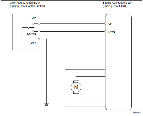
Wiring diagram
Inspection procedure
- Perform active test by intelligent tester (sliding roof operation)
- Select the active test, use the intelligent tester to generate a control command, and then check that the sliding roof operates normally.
Sliding roof ecu
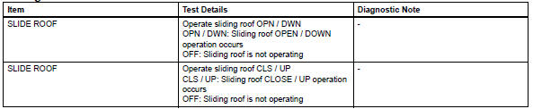
Ok: sliding roof operates normally.

- Read value of intelligent tester (sliding roof control switch)
- Use the data list to check if the sliding roof switch is functioning properly.
Sliding roof ecu
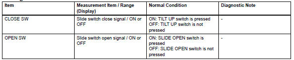
Ok: when the switch is operating, the intelligent tester should display as shown in the table.

- Check wire harness (overhead junction block - drive gear and body ground)
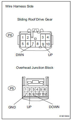
- Disconnect the p5 junction block connector.
- Disconnect the p6 drive gear connector
- Measure the resistance of the wire harness side connectors.
Standard resistance 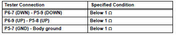

Replace overhead junction block
 Position initialization incomplete
Description
This dtc is output when the sliding roof drive gear (sliding roof ecu) has
not been initialized.
Wiring diagram
Refer to dtc b2341 (see page rf-11).
Inspection procedure
...

Other materials:
How to proceed with troubleshooting
Hint:
Use these procedures to troubleshoot the key reminder
warning system.
*: Use the intelligent tester.
Vehicle brought to workshop
Inspect battery voltage
Standard voltage:
11 to 14 v
Hint:
If the voltage is below 11 v, recharge or replace the battery
before proceedi ...
Door control switch
Inspection
Inspect power window regulator master
switch assembly (door control switch)
Measure the resistance of the door control switch.
Standard resistance
If the result is not as specified, replace the power
window regulator master switch assembly.
Inspect door control s ...
Dinghy towing
Your vehicle is not designed
to be dinghy towed (with 4
wheels on the ground)
behind a motor home.
NOTICE
â– To avoid serious damage to
your vehicle
Do not tow your vehicle with 4
wheels on the ground.
â– To prevent causing serious
damage to the transmission
and AWD system (AWD models)
2WD models: ...
