Toyota RAV4 (XA40) 2013-2018 Service Manual: Hazard warning switch circuit
Description
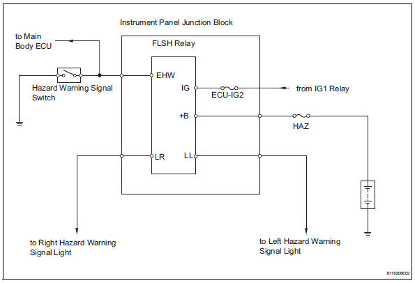
When the hazard warning signal switch is turned on, the turn signal flasher relay (marking: flsh) in the main body ecu turns on to flash the hazard warning signal lights.
Wiring diagram
Inspection procedure
- Perform active test by intelligent tester
- Connect the intelligent tester (with can vim) to the dlc3.
- Turn the ignition switch on and press the intelligent tester main switch on.
- Select the item below in the active test and then check the relay operation.

Ok: all hazard warning signal lights flash.

- Inspect fuse (haz)
- Remove the haz fuse from the engine room no. 1 Relay block.
- Measure the resistance of the fuse.
Standard resistance:
below 1


- Check wire harness (turn signal flasher relay - battery)
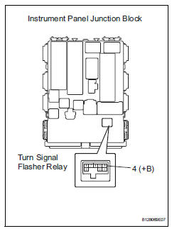
- Remove the turn signal flasher relay from the instrument panel junction block.
- Measure the voltage of the wire harness side connector.
Standard voltage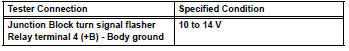

- Check operation of turn signal flasher relay (marking: flsh)
- Replace the turn signal flasher relay with a normally functioning one or a new one.
- Check that the appropriate turn signal light flashes.
- Connect the intelligent tester (with can vim) to the dlc3.
- Turn the ignition switch on and press the intelligent tester main switch on.
- Select the item below in the active test and then check the relay operation.

Ok: all hazard warning signal lights flash.

Replace turn signal flasher relay
- Inspect hazard warning signal switch
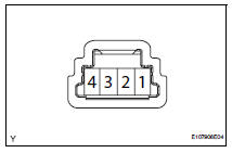
- Remove the hazard warning signal switch.
- Measure the resistance of the switch.
Standard resistance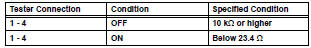

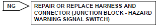
Repair or replace harness and connector (hazard warning signal switch - body ground)
 Turn signal light circuit
Description
The turn signal flasher relay (marking: flsh) in the main body ecu turns on
when it receives signals
from the headlight dimmer switch integrated with the turn signal switch, causing
...
 Back-up light circuit
Description
The park / neutral position switch turns on when the shift lever is moved
into the r position, causing the
back-up lights to illuminate.
Wiring diagram
Inspection procedure
I ...
Other materials:
Playing back mp3 and wma discs
Power
Volume
Cd eject
Selecting a file or displaying
folder list
Searching playback
Next commands, random play
or back button
Repeat play
Fast-forwarding, rewinding or
selecting a folder
Changing the audio source/
playback
Playback/pause
Previous commands
Selecti ...
Center power outlet socket (for ac power supply)
Components
Removal
Disconnect cable from negative battery
terminal
Caution:
Wait at least 90 seconds after disconnecting the
cable from the negative (-) battery terminal to
prevent airbag and seat belt pretensioner activation.
Remove console rear end panel (see page ip-
19)
...
Headlight aim
Vertical movement adjusting
bolts
Adjustment bolt A
Adjustment bolt B
Before checking the headlight
aim
Make sure the vehicle has a
full tank of gasoline and the
area around the headlight is
not deformed.
Park the vehicle on level
ground.
Make sure the tire inflation
pressure is at the ...
