Toyota RAV4 (XA40) 2013-2018 Service Manual: Back-up light circuit
Description
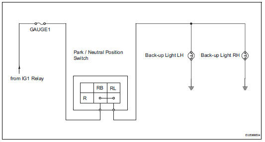
The park / neutral position switch turns on when the shift lever is moved into the r position, causing the back-up lights to illuminate.
Wiring diagram
Inspection procedure
- Inspect fuse (gauge1)
- Remove the gauge1 fuse from the instrument panel junction block.
- Measure the resistance of the fuse.
Standard resistance:
below 1

- Inspect back-up light
- Remove the rear combination light.
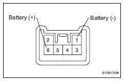
- Connect the positive (+) lead from the battery to terminal 6 and the negative (-) lead to terminal 1, then check that the light comes on.
Ok: light comes on.

- Inspect park / neutral position switch
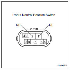
- Disconnect the b26 park / neutral position switch connector.
- Measure the resistance of the switch.
Standard resistance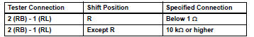

- check wire harness (park / neutral position switch - battery)
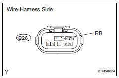
- Disconnect the b26 park / neutral position switch connector.
- Measure the voltage of the wire harness side connector.
Standard voltage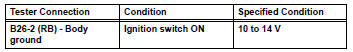

- Check wire harness (park / neutral position switch - back-up light)
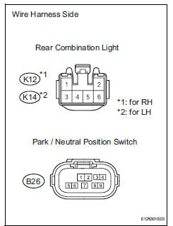
- Disconnect the b26 park / neutral position switch connector.
- Disconnect the k12 and k14 rear combination light assembly connectors
- Measure the resistance of the wire harness side connectors.
Standard resistance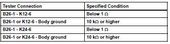

Repair or replace harness and connector (back-up light - body ground)
 Hazard warning switch circuit
Description
When the hazard warning signal switch is turned on, the turn signal flasher
relay (marking: flsh) in the
main body ecu turns on to flash the hazard warning signal lights.
Wiring diagr ...
 Light control switch circuit
Description
This circuit detects the state of the headlight dimmer switch.
Wiring diagram
Inspection procedure
Read value of intelligent tester (main body ecu)
Connect the intelligent ...
Other materials:
Torque converter clutch solenoid circuit
Description
The shift solenoid valve dsl is turned on and off by signals from the ecm to
control the hydraulic
pressure acting on the lock-up relay valve, which then controls operation of the
lock-up clutch.
Fail-safe function:
if the ecm detects a malfunction, it turns the shift sol ...
Bus ic communication malfunction
Description
The air conditioning harness connects the air conditioning amplifier and the
servos. The air conditioning
amplifier supplies power and sends operation instructions to each servo through
the air conditioning
harness. Each servo sends damper position information to the air condi ...
Diagnosis system
Description
Engine immobiliser system data and diagnostic
trouble codes (dtcs) can be read through the
vehicle's data link connector 3 (dlc3). In some
cases, a malfunction may be occurring in the engine
immobiliser system even though the security
indicator light is not illuminated ...
