Toyota RAV4 (XA40) 2013-2018 Service Manual: Camshaft position "A"
Dtc
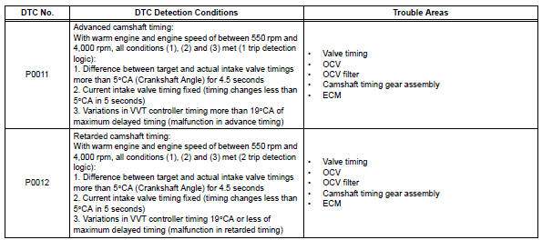
P0011 Camshaft position "a" - timing over-advanced or system performance (bank 1)
Dtc
P0012 Camshaft position "a" - timing over-retarded (bank 1)
Description
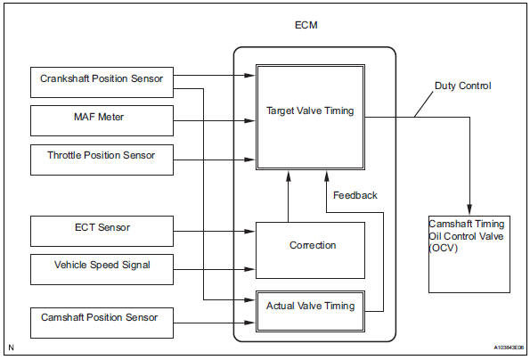
The vvt system includes the ecm, oil control valve (ocv) and vvt controller. The ecm sends a target duty-cycle control signal to the ocv. This control signal regulates the oil pressure supplied to the vvt controller. Camshaft timing control is performed according to engine operating conditions such as the intake air volume, throttle valve position and engine coolant temperature. The ecm controls the ocv, based on the signals transmitted by several sensors. The vvt controller regulates the intake camshaft angle using oil pressure through the ocv. As a result, the relative positions of the camshaft and crankshaft are optimized, the engine torque and fuel economy improve, and the exhaust emissions decrease under overall driving conditions. The ecm detects the actual intake valve timing using signals from the camshaft and crankshaft position sensors, and performs feedback control. This is how the target intake valve timing is verified by the ecm.
Monitor description
The ecm optimizes the intake valve timing using the vvt (variable valve timing) system to control the intake camshaft. The vvt system includes the ecm, the oil control valve (ocv) and the vvt controller.
The ecm sends a target duty-cycle control signal to the ocv. This control signal regulates the oil pressure supplied to the vvt controller. The vvt controller can advance or retard the intake camshaft.
If the difference between the target and actual intake valve timings is large, and changes in the actual intake valve timing are small, the ecm interprets this as the vvt controller stuck malfunction and sets a dtc.
Example:
A dtc is set when the following conditions 1, 2 and 3 are met:
- The difference between the target and actual intake valve timing is more than 5°ca (crankshaft angle) and the condition continues for more than 4.5 Seconds.
- It takes 5 seconds or more to change the valve timing by 5°ca.
- After above conditions 1 and 2 are met, the ocv is forcibly activated 63 times or more.
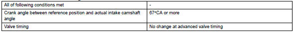
Dtc p0011 (advanced cam timing) is subject to 1 trip detection logic.
Dtc p0012 (retarded cam timing) is subject to 2 trip detection logic.
These dtcs indicate that the vvt controller cannot operate properly due to ocv malfunctions or the presence of foreign objects in the ocv.
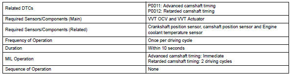
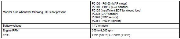
The monitor will run if all of the following conditions are met:
- The engine is warm (the engine coolant temperature is 75°c [167°f] or more).
- The vehicle has been driven at more than 64 km/h (40 mph) for 3 minutes.
- The engine has idled for 3 minutes.
Monitor strategy
Typical enabling conditions
Typical malfunction thresholds
Advanced camshaft timing:
Retard camshaft timing:
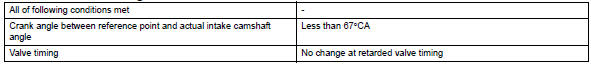
If the difference between the target and actual camshaft timings is greater than the specified value, the ecm operates the vvt actuator.
Then, the ecm monitors the camshaft timing change for 5 seconds.
Wiring diagram
Refer to dtc p0010 (see page es-64).
Inspection procedure
Notice:
Dtc p0011 or p0012 may be set when foreign objects in the engine oil are caught in some parts of the system. The dtc will remain set even if the system returns to normal after a short time.
Foreign objects are filtered out by the oil filter.
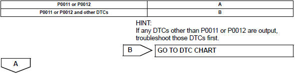
Hint:
If dtc p0011 or p0012 is present, check the vvt (variable valve timing) system.
Read freeze frame data using the intelligent tester. Freeze frame data records the engine condition when malfunctions are detected. When troubleshooting, freeze frame data can help determine if the vehicle was moving or stationary, if the engine was warmed up or not, if the air-fuel ratio was lean or rich, and other data from the time the malfunction occurred.
- Check any other dtcs output (in addition to dtc p0011 or p0012)
- Connect the intelligent tester to the dlc3.
- Turn the ignition switch on and turn the tester on.
- Select the following menu items: diagnosis / enhanced obd ii / dtc info / current codes.
- Read dtcs.
![]()
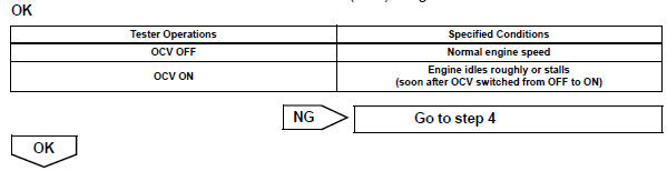
- Perform active test using intelligent tester (operate ocv)
- Connect the intelligent tester to the dlc3.
- Start the engine and turn the tester on.
- Warm up the engine.
- On the tester, select the following menu items: diagnosis / enhanced obd ii / active test / vvt ctrl b1.
- Check the engine speed while operating the oil control valve (ocv) using the tester.
- Check whether dtc output recurs (dtc p0011 or p0012)
- Connect the intelligent tester to the dlc3.
- Turn the ignition switch on and turn the tester on.
- Clear dtcs (see page es-35).
- Start the engine and warm it up.
- Switch the ecm from normal mode to check mode using the tester.
- Drive the vehicle for more than 10 minutes.
- Read dtcs using the tester.
Ok: no dtc output.

- Check valve timing (check for loose and jumped teeth on timing chain)
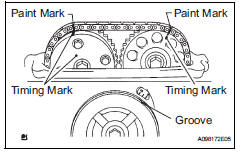
- Remove the cylinder head cover.
- Turn the crankshaft pulley, and align its groove with the timing mark "0" on the timing chain cover.
- Check that the timing marks on the camshaft timing
sprocket and camshaft timing gear are facing upward as
shown in the illustration.
If not, turn the crankshaft 1 revolution (360°), then align the marks as above.
Ok:
Timing marks on camshaft timing gears are aligned as shown in the illustration.
- Reinstall the cylinder head cover.

- Inspect camshaft timing oil control valve assembly (ocv)
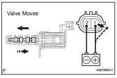
- Remove the ocv.
- Measure the resistance between the terminals of the ocv.
Standard resistance: 6.9 To 7.9 ٠at 20°c (68°f)
- Apply the positive battery voltage to terminal 1 and negative battery voltage to terminal 2. Check the valve operation.
Ok: valve moves quickly.
- Reinstall the ocv.
- Inspect oil control valve filter
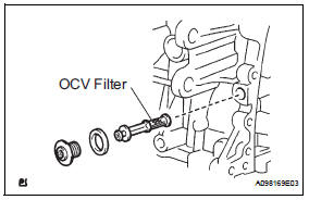
- Remove the generator.
- Remove the ocv filter.
- Check that the filter is not clogged.
Ok: filter is not clogged.
- Reinstall the ocv filter.
- Reinstall the generator.


- Replace camshaft timing gear assembly

- Check whether dtc output recurs
- Connect the intelligent tester to the dlc3.
- Turn the ignition switch on and turn the tester on.
- Clear dtcs (see page es-35).
- Start the engine and warm it up.
- Switch the ecm from normal mode to check mode using the tester.
- Drive the vehicle for more than 10 minutes.
- Read output dtcs using the tester.
Standard: no dtc output.
Hint:
Dtc p0011 or p0012 is output when foreign objects in engine oil are caught in some parts of the system. These codes will stay registered even if the system returns to normal after a short time. These foreign objects are then captured by the oil filter, thus eliminating the source of the problem.
 Camshaft position "a" actuator circuit (bank 1)
Dtc P0010 Camshaft
position "a" actuator circuit (bank
1)
Description
The variable valve timing (vvt) system includes the ecm, ocv and vvt
controller. The ecm sends a
target du ...
 Camshaft position correlation (bank 1 sensor a)
Dtc P0016 P0016 crankshaft position - camshaft position correlation
(bank 1 sensor a)
Description
In the vvt (variable valve timing) system, the appropriate intake valve open
and close timing is
...
Other materials:
Side airbag sensor
Components
On-vehicle inspection
Check side airbag sensor (vehicle not
involved in collision)
Perform a diagnostic system check (see page rs-
49).
Check side airbag sensor (vehicle involved
in collision and airbag has not deployed)
Perform a diagnostic system check ( ...
Oxygen (a/f) sensor signal stuck
Hint:
Although the dtc titles say oxygen sensor, these dtcs relate to the
air-fuel ratio (a/f) sensor.
Sensor 1 refers to the sensor mounted in front of the three-way
catalytic converter (twc) and
located near the engine assembly.
Description
The a/f sensor generates a voltage* ...
Transmission oil cooler
Components
Removal
Remove transmission oil cooler
*1: Disconnect the no. 3 Water by-pass hose from
the transmission oil cooler.
*2: Disconnect the no. 4 Water by-pass hose from
the transmission oil cooler.
*3: Disconnect the no. 1 Oil cooler inlet hose from
the transmiss ...
