Toyota RAV4 (XA40) 2013-2018 Service Manual: Ts and cg terminal circuit
Description
If the vehicle is stationary during sensor check mode, speed sensor malfunctions cannot be detected. The vehicle must be driven for speed sensor malfunctions to be detected.
Hint:
Change to sensor check mode by connecting terminals tc and cg of the dlc3, and turning the ignition switch from off to on.
Wiring diagram
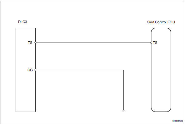
Inspection procedure
- Check wire harness (dlc3 - skid control ecu and body ground)
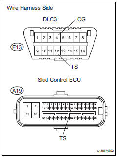
- Disconnect the a27 ecu connector.
- Measure the resistance of the wire harness side connectors.
Standard resistance 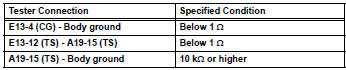

Replace abs and traction actuator assembly
 Tc and cg terminal circuit
Description
Connecting terminals tc and cg of the dlc3 causes the skid control ecu to
display 2-digit dtcs by
flashing the abs warning light.
Wiring diagram
Inspection procedure
Check dl ...
 Abs and traction actuator
Components
...
Other materials:
Yaw rate sensor communication stop mode
Description
Wiring diagram
Inspection procedure
Notice:
Turn the ignition switch off before measuring the resistances of the
main wire and the branch
wire.
After the ignition switch is turned off, check that the key reminder
warning system and light
reminder warning system ...
Removal
Disconnect cable from negative battery
terminal
Caution:
Wait at least 90 seconds after disconnecting the
cable from the negative (-) battery terminal to
prevent airbag and seat belt pretensioner activation.
Remove fan and generator v belt
Remove the belt (see page em-6).
...
Wheels
If a wheel is bent, cracked or
heavily corroded, it should
be replaced. Otherwise, the
tire may separate from the
wheel or cause a loss of
handling control.
Wheel selection
When replacing wheels, care
should be taken to ensure that
they are equivalent to those
removed in load capacity, diameter,
rim ...
