Toyota RAV4 (XA40) 2013-2018 Service Manual: Abs and traction actuator
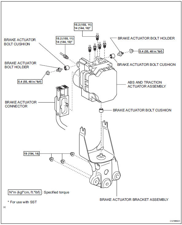
Components
 Ts and cg terminal circuit
Description
If the vehicle is stationary during sensor check mode, speed sensor
malfunctions cannot be detected. The
vehicle must be driven for speed sensor malfunctions to be detected.
Hint:
...
 On-vehicle inspection
Connect intelligent tester
Connect the intelligent tester to the dlc3.
Start the engine and idle it.
Select the active test mode on the intelligent tester.
Hint:
Please refer to t ...
Other materials:
Terminals of ecu
Check sliding roof drive gear subassembly (sliding roof ecu)
Disconnect the p6 ecu connector.
Measure the resistance and voltage of the wire
harness side connector.
Reconnect the p6 ecu connector.
Measure the voltage of the connector.
If the result is not as speci ...
Starting system
Parts location
System diagram
The starting system rotates the starter motor according to the
signals from the ignition switch and pnp switch.
...
Front seat frame with adjuster
Inspection
Inspect front seat frame with adjuster
Check operation of the seat frame (slide motor).
Check if the seat frame moves smoothly when
the battery is connected to the slide motor
connector terminals.
Ok
If the result is not as specified, replace the seat
frame w ...
