Toyota RAV4 (XA40) 2013-2018 Service Manual: Installation (2005/11-2006/01)
- Install abs and traction actuator assembly with bracket
Notice:
Do not remove the hole plug before connecting the brake tube. New actuators are filled with brake fluid.
- Install the actuator with bracket with the 3 nuts.
Torque: 19 n*m (194 kgf*cm, 14 ft.*Lbf)
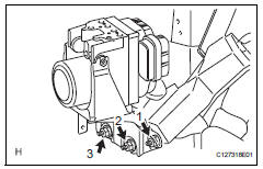
Hint:
The nuts should be tightened in order from 1 to 3 as shown in the illustration.
Notice:
Be careful not to damage the brake tubes.
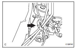
- Connect the brake tube clamp to the bracket.
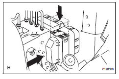
- Connect the connector and push the lock lever downward.
- Connect brake lines
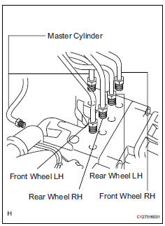
- Using sst, connect the 6 brake lines to the correct locations on the actuator, as shown in the illustration.
Sst 09023-00101
Torque: 15.2 N*m (155 kgf*cm, 11 ft.*Lbf) without sst
14 N*m (144 kgf*cm, 10 ft.*Lbf) with sst
Hint:
Use a torque wrench with a fulcrum length of 30 cm (11.81 In.).
- Fill reservoir with brake fluid (see page br- 6)
- Bleed air from brake master cylinder (see page br-7)
- Bleed air from brake line (see page br-7)
- Bleed air from abs and traction actuator assembly (see page br-8)
- Check brake fluid level in reservoir (see page br-6)
- Check for brake fluid leakage
- Install air cleaner case sub-assembly
- Install the air cleaner case (see page em-105).
Hint:
Refer to the procedures from the installation of the air cleaner case up until the installation of the purge vsv.
- Connect cable to negative battery terminal
- Check abs and traction actuator assembly with intelligent tester
- Check the abs and traction actuator with the intelligent tester (see page bc-180).
 Removal (2006/01- )
Disconnect cable from negative battery
terminal
Caution:
Wait at least 90 seconds after disconnecting the
cable from the negative (-) battery terminal to
prevent airbag and seat belt preten ...
 Front speed sensor
Components
Removal
Hint:
Use the same procedures for the lh side and rh side.
The procedures listed below are for the lh side.
Disconnect cable from negative battery
terminal
Ca ...
Other materials:
Installation
Caution:
Be sure to read the precautionary notices concerning the
srs airbag system before servicing it (see page rs-1).
Install steering pad assembly
Support the steering pad with one hand as shown in
the illustration.
Connect the 2 airbag connectors.
Notice:
When handling t ...
When towing active torque control 4wd vehicles
Use one of the methods shown below to tow the
vehicle.
If the vehicle has trouble in the chassis and drivetrain,
use method 1 (flat bed truck).
Notice:
Do not use any towing method other than those
shown above.
For example, the towing methods shown below are
dangerous or dama ...
Steering angle sensor communication stop mode
Description
Wiring diagram
Inspection procedure
Notice:
Turn the ignition switch off before measuring the resistances of the
main wire and the branch
wire.
After the ignition switch is turned off, check that the key reminder
warning system and light
reminder warning system ...
