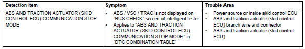
Toyota RAV4 (XA40) 2013-2018 Service Manual: Abs and traction actuator (skid control ecu) communication stop mode
Description
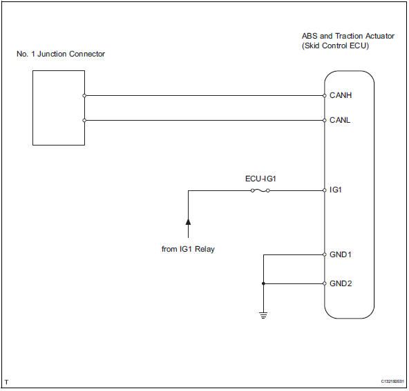
Wiring diagram
Inspection procedure
Notice:
- Turn the ignition switch off before measuring the resistances of the main wire and the branch wire.
- After the ignition switch is turned off, check that the key reminder warning system and light reminder warning system are not in operation.
- Before measuring the resistance, leave the vehicle for at least 1 minute and do not operate the ignition switch, any switches or doors. If doors need to be opened in order to check connectors, open the doors and leave them open.
Hint:
Operating the ignition switch, any switches or any doors triggers related ecu and sensor communication with the can, which causes resistance variation.
- Check can bus line disconnection (abs and traction actuator branch wire)
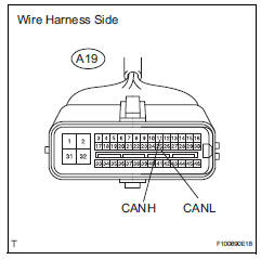
- Disconnect the a19 abs and traction actuator (skid control ecu) connector.
- Measure the resistance of the wire harness side connector.
Standard resistance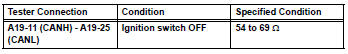

- Check wire harness (abs and traction actuator - battery and body ground)
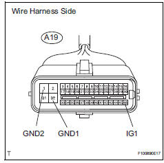
- Disconnect the a19 abs and traction actuator (skid control ecu) connector.
- Measure the resistance of the wire harness side connector.
Standard resistance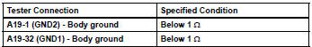
- Measure the voltage of the wire harness side connector.
Standard voltage 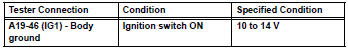

Replace abs and traction actuator (skid control ecu)
 Fail-safe chart
Fail-safe function
When communication fails in any of the main wires
(communication lines) due to a short circuit or other
causes, the fail-safe function, which is specified for
each sy ...
 Air conditioning amplifier communication stop mode
Description
Wiring diagram
Inspection procedure
Notice:
Turn the ignition switch off before measuring the resistances
of the main wire and the branch
wire.
After the ignition ...
Other materials:
Tire and wheel system
Inspection
Inspect tire
Check the tires for wear and proper inflation
pressure.
Standard cold tire inflation pressure:
220 kpa (2.2 Kgf/cm2, 32 psi)
Using a dial indicator, check the runout of the tires.
Standard tire runout:
1.0 Mm (0.039 In.) Or less
Rotate tire
...
Registration
Notice:
The vehicle identification number (vin) must be input
into the replacement ecm.
Hint:
The vin is a 17-digit alphanumeric number. The intelligent
tester is required to register the vin.
Description
This registration section consists of 3 parts: input
instructions, read vin and wr ...
Console box
Lift the lid while pulling up the
lever to release the lock.
When using the console box lid as an armrest (vehicles with slide
function)
Slide the console box lid forward as
needed. Pull the lid forward by holding the
front of the lid.
Caution
Console box adjustment precaution
D ...
