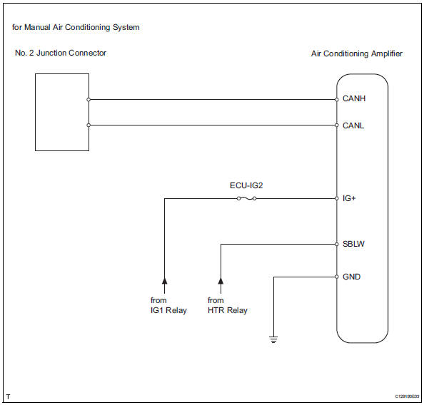
Toyota RAV4 (XA40) 2013-2018 Service Manual: Air conditioning amplifier communication stop mode
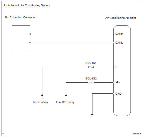
Description
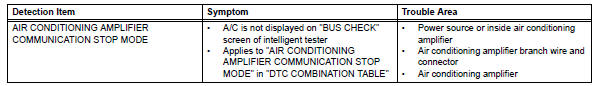
Wiring diagram
Inspection procedure
Notice:
- Turn the ignition switch off before measuring the resistances of the main wire and the branch wire.
- After the ignition switch is turned off, check that the key reminder warning system and light reminder warning system are not in operation.
- Before measuring the resistance, leave the vehicle for at least 1 minute and do not operate the ignition switch, any switches or doors. If doors need to be opened in order to check connectors, open the doors and leave them open.
Hint:
Operating the ignition switch, any switches or any doors triggers related ecu and sensor communication with the can, which causes resistance variation.
- Check can bus line for disconnection (air conditioning amplifier branch wire)
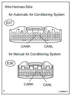
- Disconnect the e37*1 or e36*2 air conditioning amplifier connector.
Hint:
- *1: For automatic air conditioning system.
- *2: For manual air conditioning system.
- Measure the resistance of the wire harness side connector.
Standard resistance:
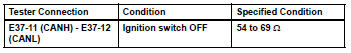
for automatic air conditioning system
For manual air conditioning system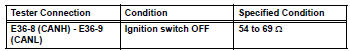

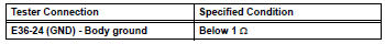
- Check wire harness (air conditioning amplifier - battery and body ground)
- Disconnect the e37*1 or e36*2 air conditioning amplifier connector.
Hint:
- *1: For automatic air conditioning system.
- *2: For manual air conditioning system.
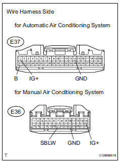
- Measure the resistance of the wire harness side connectors.
Standard resistance:
for automatic air conditioning system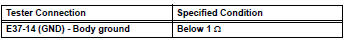
For manual air conditioning system
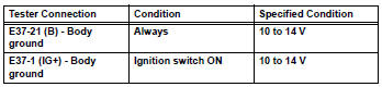
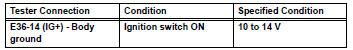
- Measure the voltage of the wire harness side connector.
Standard voltage:
for automatic air conditioning system
For manual air conditioning system

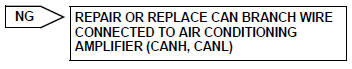
Replace air conditioning amplifier
 Abs and traction actuator (skid control ecu) communication stop mode
Description
Wiring diagram
Inspection procedure
Notice:
Turn the ignition switch off before measuring the resistances
of the main wire and the branch
wire.
After the ignition swi ...
 Power steering ecu communication stop mode
Description
Wiring diagram
Inspection procedure
Notice:
Turn the ignition switch off before measuring the resistances of the
main wire and the branch
wire.
After the ignition swi ...
Other materials:
Lubrication system
On-vehicle inspection
Check engine oil level
Warm up the engine, stop the engine and wait for 5
minutes.
Check that the engine oil level is between the l and
f marks of the oil dipstick.
If low, check for leakage and add oil up to the f
mark.
Notice:
Do not add engine oil a ...
Fail-safe chart
Fail safe operation
If there is a problem with any sensor signals or
actuator systems, the skid control ecu prohibits the
power supply to the abs and traction actuator
and informs the ecm of vsc system failure.
The abs and traction actuator turns off the
solenoids and the ecm sh ...
Short to b+ in can bus line
Description
There may be a short circuit between the can bus line and +b when there is
resistance between
terminals 6 (canh) and 16 (bat) or terminals 14 (canl) and 16 (bat) of the dlc3.
Wiring diagram
Inspection procedure
Notice:
Turn the ignition switch off before measuring ...
