Toyota RAV4 (XA40) 2013-2018 Service Manual: Air mix damper control servo motor circuit (driver side)

Description
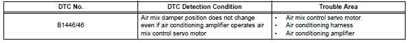
The air mix damper servo sends pulse signals to indicate the damper position to the air conditioning amplifier. The air conditioning amplifier activates the motor (normal or reverse) based on these signals to move the air mix damper (driver seat) to the appropriate position. This adjusts the amount of air passing through the heater core after passing the evaporator and controls the temperature of the blown air.
Hint:
Confirm that there are no mechanical problems because this dtc can be output when either a damper link or damper is mechanically locked.
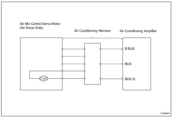
Wiring diagram
Inspection procedure
- Read value of intelligent tester (air mix servo targ pulse (d))
- Connect the intelligent tester (with can vim) to the dlc3.
- Turn the ignition switch on and turn the intelligent tester main switch on.
- Select the items below in the data list, and read the value displayed on the intelligent tester.
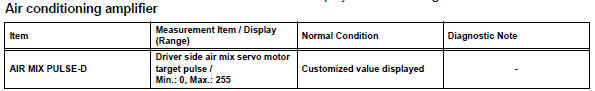
Ok: the display is as specified in the normal condition column.
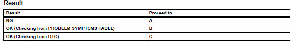

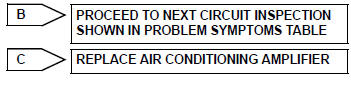
- Replace air mix control servo motor
Hint:
Since the servo motor cannot be tested when it is removed from the vehicle, replace the servo motor with a normal one and check that the condition returns to normal.
Ok: same problem does not occur.

System is ok
 Air outlet damper control servo motor circuit
Description
The damper servo sends pulse signals to indicate the damper position to the
air conditioning amplifier.
The air conditioning amplifier activates the motor (normal or reverse) bas ...
 Compressor solenoid circuit (2005/11-2006/01)
Description
In this circuit, the compressor receives a refrigerant compression demand
signal from the air conditioning
amplifier. Based on this signal, the compressor changes the degree of
r ...
Other materials:
Outside vehicle
General maintenance
Performing the following maintenance checks on the vehicle
is the owner's responsibility. The owner may perform the
maintenance or take the vehicle to a service center. Check
the parts of the vehicle described below on a daily basis. In
most cases, special tools are not requ ...
Engine (ignition) switch
(vehicles without smart
key system)
Starting the engine
1. Pull the parking brake switch
to check that the parking
brake is set.
The parking brake indicator will
come on.
2. Check that the shift lever is
set in P.
3. Firmly depress the brake
pedal.
4. Turn the engine switch to
START to start the engine.
â– If the engine does not s ...
Removal
Caution:
Be sure to read the precautionary notices concerning the
srs airbag system before servicing it (see page rs-1).
Disconnect cable from negative battery
terminal
Caution:
Wait at least 90 seconds after disconnecting the
cable from the negative (-) battery terminal to
prevent air ...
