Toyota RAV4 (XA40) 2013-2018 Service Manual: Check mode procedure
Hint:
Intelligent tester only: compared to normal mode, check mode is more sensitive to malfunctions. Therefore, check mode can detect the malfunctions that cannot be detected by normal mode.
Notice:
All the stored dtcs and freeze frame data are erased if:
- The ecm is changed from normal mode to check mode or vice versa;
- Or the ignition switch is turned from on to acc or off while in check mode. Before changing modes, always check and make a note of any dtcs and freeze frame data.
- Check mode procedure (using intelligent tester)
- Check and ensure the following conditions:
- Battery positive voltage 11 v or more.
- Throttle valve fully closed.
- Transmission in the p or n position.
- A/c switch off.
- Turn the ignition switch off.
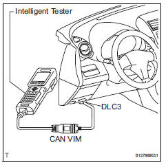
- Connect the intelligent tester to the dlc3.
- Turn the ignition switch on.
- Turn the tester on.
- Select the following menu items: diagnosis / enhanced obd ii/ check mode.
- Switch the ecm from normal mode to check mode.
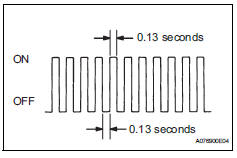
Make sure the mil flashes as shown in the illustration.- Start the engine.
- Make sure the mil turns off.
- Simulate the conditions of the malfunction described by the customer.
- Check dtcs and freeze frame data using the tester.
 Freeze frame data
Description
Freeze frame data records the engine conditions (fuel
system, calculated load, engine coolant temperature,
fuel trim, engine speed, vehicle speed, etc.) When a
malfunction is dete ...
 Fail-safe chart
If any of the following dtcs are set, the ecm enters fail-safe
mode to allow the vehicle to be driven temporarily.
Hint:
*: The vehicle can be driven slowly when the accelerator
pedal is depre ...
Other materials:
System too
Description
The fuel trim is related to the feedback compensation value, not to the basic
injection time. The fuel trim
consists of both the short-term and the long-term fuel trims.
The short-term fuel trim is fuel compensation that is used to constantly
maintain the air-fuel ratio at
...
Removal
Caution:
Be sure to read the precautionary notices concerning the
srs airbag system before servicing it (see page rs-1).
Disconnect cable from negative battery
terminal
Caution:
Wait at least 90 seconds after disconnecting the
cable from the negative (-) battery terminal to
prevent air ...
Canister
Components
removal
Disconnect cable from negative battery
terminal
Caution:
Wait at least 90 seconds after disconnecting the
cable from the negative (-) battery terminal to
prevent airbag and seat belt pretensioner activation.
Remove canister
Disconnect the 2 tubes, hose a ...
