
Toyota RAV4 (XA40) 2013-2018 Service Manual: System description
- Description of system
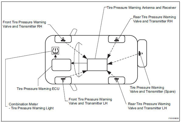
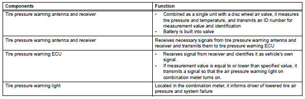
- A tire pressure warning antenna and receiver is equipped with a tire pressure sensor and a transmitter and is installed in each tire wheel. The sensor measures the tire pressure and internal temperature of the tire. Then the measured value and transmitter id are transmitted to the tire pressure monitor receiver on the body as radio waves, which are sent to the tire pressure warning ecu. If the transmitter id has already been registered, the ecu compares the measured air pressure value with the standard value. When the value is less than the standard value registered in the tire pressure warning ecu, the warning light in the combination meter turns on.
- When tire pressure warning light is lit
- When the tire pressure warning light does not turn off, or when it turns on during driving, check the tire pressure. If the tire pressure warning light turns on within several hours after adjusting the tire pressure, the tire may have a slow air leak.
- Under the following conditions, the system may not function properly;
- Areas, facilities or devices that use similar radio frequencies are located in the vicinity of the vehicle.
- Devices using similar radio frequencies are used in the vehicle.
- Large amounts of snow or ice are stuck to the vehicle, especially on the wheels and around the wheel houses.
- The battery of the transmitter is depleted.
- Tires and wheels without tire pressure warning valves and transmitters are used.
- Snow tires and tire chains are used.
- If wheels other than the specified ones are used, the system may not function properly because different radio waves are transmitted from the tire pressure warning valve and transmitter.
- Depending on the tire type, the tire pressure warning valve and transmitter may not function properly even though the specified wheels are used.
- The system may not function properly if it is initialized with tire pressures which are not the specified values.
- The average life of the grommet of the tire pressure warning antenna and receiver is approximately 5 years, at which time it must be replaced. Retighten the valve nut if the valve is leaking air, if it is less than 5 years old, and there is no problem with the grommets.
- After removing and installing the ecu or a sensor, output a diagnosis code and check that it is a normal code.
- Function of components
 Parts location
System diagram
...
 How to proceed with troubleshooting
Hint:
Use these procedures to troubleshoot the tire pressure
warning system.
*: Use the intelligent tester.
Vehicle brought to workshop
Inspect battery voltage
Standard volta ...
Other materials:
Installation
Install upper instrument panel
Attach the 6 clips and 5 claws to install the
instrument panel.
Connect the connectors and clamps.
Install the 2 bolts and 2 screws.
Connect the passenger airbag connector.
Install the 2 bolts to the passenger airbag.
Torque: 20 n*m (204 k ...
Air inlet damper control servo motor circuit
Description
The damper servo (air inlet control) sends pulse signals to indicate the
damper position to the air
conditioning amplifier. The air conditioning amplifier activates the motor
(normal or reverse) based on
these signals to move the air inlet control damper to the appropriate pos ...
Downhill assist control operation switch (test mode dtc)
Description
The downhill assist control switch is connected to the skid control ecu in
the abs and traction
actuator.
Dtc c1379/74 can be detected when the downhill assist control switch sends the
downhill assist control
switch signal or test mode ends. Dtc c1379/74 is output only in t ...
