Toyota RAV4 (XA40) 2013-2018 Service Manual: Check mode procedure
- Panel diagnosis (indicator check)
- Turn the ignition switch to lock.
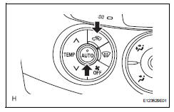
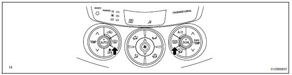
- Turn the ignition switch on while simultaneously pressing the a/c control auto switch and the rec/ frs switch.
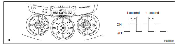
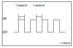
- Check that all indicators and the display area are turned on and off 4 times in succession at 1 second intervals.
Hint:
After the indicator check is completed, the system automatically enters sensor check mode.
- Press the off switch to terminate the panel diagnosis.
- Panel diagnosis (sensor check)
- Perform the indicator check.
Hint:
After the indicator check is completed, the system automatically enters sensor check mode.
- Press the rec/frs switch to enter actuator check mode.
- After the actuator check is completed, press the auto switch to enter sensor check mode.
Notice:
The sensor check must be performed again after the actuator check is completed because sensor check mode, which starts automatically after the indicator check, cannot fully detect malfunctions.
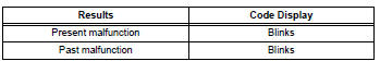
- Check the sensor check results displayed on the set
temperature display.
Hint:
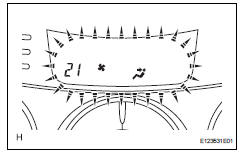
- The illustration shows the display when code 21 is output.
- When 2 or more sensor check codes are detected, the codes are displayed in ascending numerical order.
- In cases with 2 or more codes, if they are difficult to read, press the def switch to activate the step operation and display them one by one.
- The codes are displayed in ascending numerical order as the def switch is pressed.
- When any sensor check codes are displayed, refer to the dtc chart (see page ac-39).
- Press the off switch to terminate the panel diagnosis.
Hint:
Pressing the rec/frs switch returns the system to actuator check mode.
- Panel diagnosis (clear sensor check code)
- Inspect, and repair or replace the malfunctioning parts.
- Clear the sensor check codes.
- While pressing the def switch during sensor check mode, press the rr def switch.
Hint:
Sensor check codes can be cleared by removing the ecu-b2 fuse from the engine room no. 2 Relay block for more than 60 seconds.
- Perform the sensor check and confirm that normal code 00 is displayed.
- Panel diagnosis (actuator check)
- Start the engine and warm it up.
- Perform the indicator check.
- When the sensor check is started after the indicator check, press the rec/frs switch to start the actuator check.
Hint:
Perform the actuator check with the engine running.
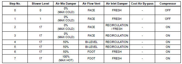
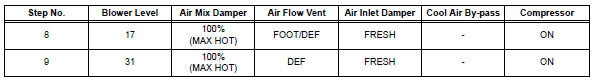
- Check the temperature and blower levels by hand at each step while the actuator check proceeds from step 0 to 9 at 1 second intervals (continuous operation).
Hint:
Each step number is displayed on the set temperature display.
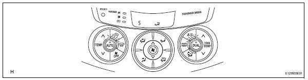
- To display step numbers one by one manually,
press the def switch to activate the step operation.
The step number changes each time the def switch is pressed.
Hint:
- Each step number blinks at 1 second intervals during the step operation.
- The illustration shows the display when step number 5 is displayed.
- Press the off switch to terminate the panel diagnosis.
Hint:
Pressing the auto switch returns to sensor check mode.
 Dtc check / clear
Check dtc
Connect the intelligent tester (with can vim) to the
dlc3.
Turn the ignition switch on and turn the intelligent
tester on.
Read the dtc by following the prompts on the
...
 Data list / active test (2005/11-2006/01)
Read data list
Read data list
Hint:
Using the intelligent tester's data list allows switch,
sensor, actuator and other item values to be read without
removing any parts. Reading the ...
Other materials:
Check mode procedure
Check mode (signal check)
Connect the intelligent tester (with can vim) to the
dlc3.
Turn the ignition switch on.
Select the "signal check", and continue
checking with the intelligent tester.
Notice:
Select the "signal check" from the "dtc
check&quo ...
Underdrive clutch
Components
Disassembly
Inspect pack clearance of underdrive
clutch (see page ax-247)
Remove no. 1 Underdrive clutch disc
Using a screwdriver, pry out the underdrive clutch
flange snap ring.
Remove the flange, 3 discs and 3 plates from the
underdrive clutch drum.
In ...
Catalyst monitor (active air-fuel ratio control type)
Preconditions
The monitor will not run unless:
The mil is off.
Drive pattern
Connect the intelligent tester to the dlc3.
Turn the ignition switch on.
Turn the tester on.
Clear dtcs (if set) (see page es-35).
Start the engine and warm it up.
Drive the vehicle at be ...
