Toyota RAV4 (XA40) 2013-2018 Service Manual: Coolant thermostat (coolant temperature below thermostat regulating temperature)

Hint:
This dtc relates to the thermostat.
Description
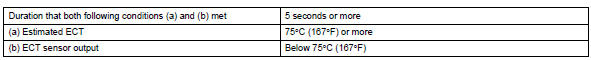
This dtc is set when the engine coolant temperature (ect) does not reach 75°c (167°f) despite sufficient engine warm-up time having elapsed.
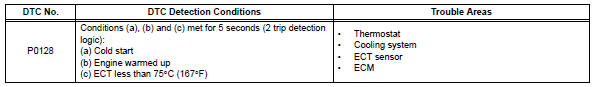
Monitor description
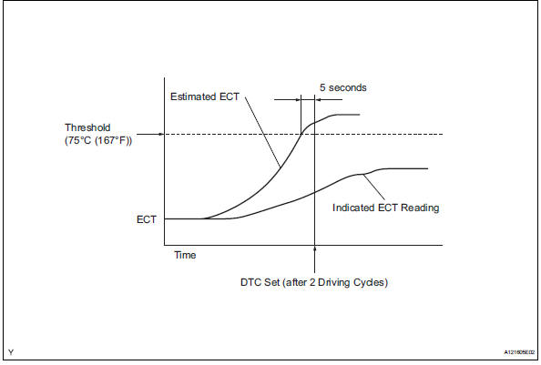
The ecm estimates the ect based on the starting temperature, engine loads, and engine speeds. The ecm then compares the estimated temperature with the actual ect. When the estimated ect reaches 75°c (167°f), the ecm checks the actual ect. If the actual ect is less than 75°c (167°f), the ecm interprets this as a malfunction in the thermostat or the engine cooling system and sets the dtc.
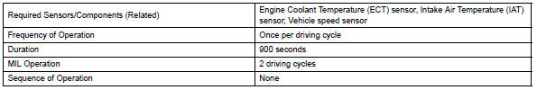
Monitor strategy
![]()
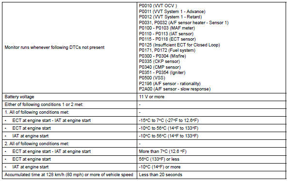
Typical enabling conditions
Typical malfunction thresholds
Inspection procedure
Hint:
Read freeze frame data using the intelligent tester. Freeze frame data records the engine condition when malfunctions are detected. When troubleshooting, freeze frame data can help determine if the vehicle was moving or stationary, if the engine was warmed up or not, if the air-fuel ratio was lean or rich, and other data from the time the malfunction occurred.
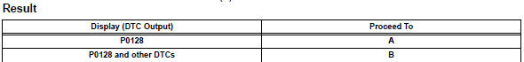
- Check any other dtcs output (in addition to dtc p0128)
- Connect the intelligent tester to the dlc3.
- Turn the ignition switch on.
- Turn the tester on.
- Select the following menu items: diagnosis / enhanced obd ii / dtc info / current codes.
- Read dtcs.
Hint:
If any dtcs other than p0128 are output, troubleshoot those dtcs first.


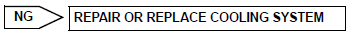
- Check cooling system
- Check for defects in the cooling system that might cause the system to be too cold, such as abnormal radiator fan operation or any modifications.

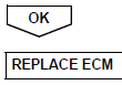
- Inspect thermostat
- Remove the thermostat (see page co-15).
- Measure the valve opening temperature of the thermostat.
Standard value: 80 to 84°c (176 to 183°f)
Hint:
In addition to the above check, confirm that the valve is completely closed when the temperature is below the standard.
- Reinstall the thermostat (see page co-15).
 Insufficient coolant temperature for closed loop fuel control
Description
Refer to dtc p0115 (see page es-105).
Monitor description
The resistance of the ect sensor varies in proportion to the actual ect. The
ect supplies a constant
voltage to the ...
 Oxygen sensor circuit
Description
In order to obtain a high purification rate of the carbon monoxide (co),
hydrocarbon (hc) and nitrogen
oxide (nox) components in the exhaust gas, a twc is used. For the most effici ...
Other materials:
System description
Description of system
A tire pressure warning antenna and receiver is
equipped with a tire pressure sensor and a
transmitter and is installed in each tire wheel. The
sensor measures the tire pressure and internal
temperature of the tire. Then the measured value
and transmitter id ...
Hill-start assist control
When the engine is stopped by
the Stop & Start system when
the vehicle is on an incline,
when the brake pedal is
released, brake force is temporarily
maintained to prevent the
vehicle from rolling backwards
before the engine is restarted
and drive force is generated.
When drive force is generat ...
Headlight (hi-beam) circuit
Description
The body ecu controls the headlight relay, no. 2 Daytime running light relay
(marking: drl no. 2) And
no. 4 Daytime running light relay (marking: drl no. 4).
Wiring diagram
Inspection procedure
Perform active test by intelligent tester
Connect the intelligent test ...
