Toyota RAV4 (XA40) 2013-2018 Service Manual: Insufficient coolant temperature for closed loop fuel control
Description
Refer to dtc p0115 (see page es-105).
Monitor description
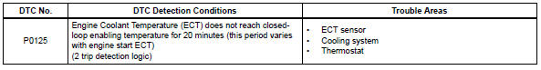
The resistance of the ect sensor varies in proportion to the actual ect. The ect supplies a constant voltage to the sensor and monitors the signal output voltage of the sensor. The signal voltage output varies according to the changing resistance of the sensor. After the engine is started, the ect is monitored through this signal. If the ect sensor indicates that the engine is not yet warm enough for closed-loop fuel control, despite a specified period of time having elapsed since the engine was started, the ecm interprets this as a malfunction in the sensor or cooling system and sets the dtc.
Example: the ect is 0°c (32°f) at engine start. After about 1 minute running time, the ect sensor still indicates that the engine is not warm enough to begin closed-loop fuel (air-fuel ratio feedback) control. The ecm interprets this as a malfunction in the sensor or cooling system and sets the dtc.
Monitor strategy
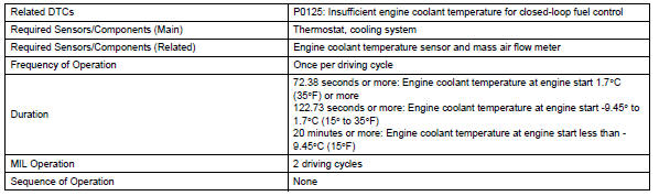
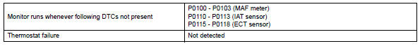
Typical enabling conditions
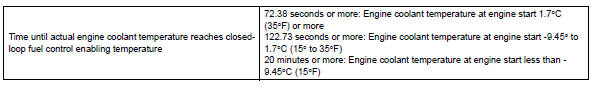
Typical malfunction thresholds
Wiring diagram
Refer to dtc p0115 (see page es-106).
Inspection procedure
Hint:
- If any of dtcs p0115, p0116, p0117 or p0118 are set simultaneously with dtc p0125, the engine coolant temperature (ect) sensor may have an open or a short circuit. Troubleshoot those dtcs first.
- Read freeze frame data using the intelligent tester. Freeze frame data records the engine condition when malfunctions are detected. When troubleshooting, freeze frame data can help determine if the vehicle was moving or stationary, if the engine was warmed up or not, if the air-fuel ratio was lean or rich, and other data from the time the malfunction occurred.
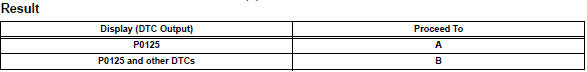
- Check any other dtcs output (in addition to dtc p0125)
- Connect the intelligent tester to the dlc3.
- Turn the ignition switch on.
- Turn the tester on.
- Select the following menu items: diagnosis / enhanced obd ii / dtc info / current codes.
- Read dtcs.
Hint:
If any dtcs other than p0125 are output, troubleshoot those dtcs first.


- Inspect thermostat
- Remove the thermostat (see page co-15).
- Check the valve opening temperature of the thermostat.
Standard value: 80 to 84°c (176 to 183°f)
Hint:
In addition to the above check, confirm that the valve is completely closed when the temperature is below the standard.
- Reinstall the thermostat (see page co-15).


- Check cooling system
- Check for defects in the cooling system that might cause the system to be too cold, such as abnormal radiator fan operation or any modifications.

 Throttle / pedal position sensor / switch "A" circuit range / performance
problem
Throttle / pedal position sensor / switch "A" circuit range / performance
problem
Hint:
This dtc relates to the throttle position (tp) sensor.
Description
Refer to dtc p0120 (see page es-114).
Monitor description
The ecm uses the tp sensor to monitor the throttle valve ...
 Coolant thermostat (coolant temperature below thermostat regulating
temperature)
Coolant thermostat (coolant temperature below thermostat regulating
temperature)
Hint:
This dtc relates to the thermostat.
Description
This dtc is set when the engine coolant temperature (ect) does not reach 75°c
(167°f) despite
sufficient engine warm-up time having el ...
Other materials:
Steering angle sensor
Components
Removal
Precaution
Caution:
Be sure to read the "precaution" thoroughly
before servicing (see page rs-1).
Disconnect cable from negative battery
terminal
Caution:
Wait at least 90 seconds after disconnecting the
cable from the negative (-) battery termin ...
Installation
Caution:
Be sure to read the precautionary notices concerning the
srs airbag system before servicing it (see page rs-1).
Install steering pad assembly
Support the steering pad with one hand as shown in
the illustration.
Connect the 2 airbag connectors.
Notice:
When handling t ...
When towing active torque control 4wd vehicles
Use one of the methods shown below to tow the
vehicle.
If the vehicle has trouble in the chassis and drivetrain,
use method 1 (flat bed truck).
Notice:
Do not use any towing method other than those
shown above.
For example, the towing methods shown below are
dangerous or dama ...
