Toyota RAV4 (XA40) 2013-2018 Service Manual: Disassembly
- Inspect oil pump assembly (see page ax-218)
- Remove clutch drum oil seal ring
- Remove the 2 clutch drum oil seal rings.
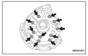
- Remove stator shaft assembly
- Using a t30 ''torx'' socket, remove the 11 bolts and stator shaft. Keep the gears in assembling order.
- Inspect clearance of oil pump assembly (see page ax-218)
- Remove front oil pump drive gear
- Remove the front oil pump drive gear.
- Remove front oil pump driven gear
- Remove the front oil pump driven gear.
- Remove front oil pump body o-ring
- Using a screwdriver, pry out the o-ring.
Hint:
Tape the screwdriver before use.
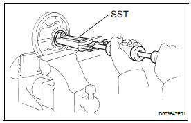
- Remove front oil pump oil seal
- Mount the oil pump in a soft jaw vise.
- Using sst, tap out the oil seal from the oil pump body.
Sst 09308-00010
- Inspect front oil pump and gear body subassembly (see page ax-219)
- Inspect stator shaft assembly (see page ax- 219)
 Oil pump
Components
...
 Inspection
Inspect oil pump assembly
Turn the drive gear with 2 screwdrivers and make
sure it rotates smoothly.
Notice:
Be careful not to damage the oil seal lip.
Inspect clearance of oil ...
Other materials:
Data list / active tes
Read data list
Hint:
Using the intelligent tester's data list allows switch,
sensor, actuator and other item values to be read without
removing any parts. Reading the data list early in
troubleshooting is one way to save time.
Connect the intelligent tester (with can vim) to the
dlc3 ...
Reassembly
Hint:
When installing the ornament plate and emblem, heat the
radiator grille, ornament plate and emblem using a heat light.
Standard heating temperature
Notice:
Do not heat the radiator grille, ornament plate and
emblem excessively.
Install radiator grille emblem
Attach ...
Turn signal lever
Operating instructions
Right turn
Lane change to the right (move
the lever partway and release
it)
the right hand signals will flash 3
times.
Lane change to the left (move
the lever partway and release
it)
the left hand signals will flash 3
times.
Left turn
Turn signals ...
