Toyota RAV4 (XA40) 2013-2018 Service Manual: Installation
Hint:
- Use the same procedures for the rh side and lh side.
- The procedures listed below are for the rh side.
- Install front seat assembly
- Place the seat in the cabin.
Notice:
Be careful not to damage the vehicle body.
- Connect the connector under the seat.
- Lift up the seat track adjusting handle and move the seat to the rearmost position.
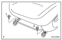
- Tighten the 2 bolts on the front side of the seat.
Torque: 37 n*m (377 kgf*cm, 27 ft.*Lbf)
Hint:
Tighten the bolts in the order indicated in the illustration.
- Lift up the seat track adjusting handle and move the seat to the foremost position.
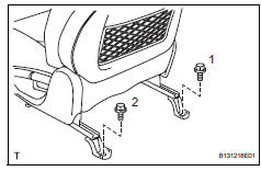
- Tighten the 2 bolts on the rear side of the seat.
Torque: 37 n*m (377 kgf*cm, 27 ft.*Lbf)
Hint:
Tighten the bolts in the order indicated in the illustration.
- Inspect and adjust seat slide adjuster locks
- During sliding operation of the front seat, check that
the left and right adjusters move together smoothly
and lock simultaneously.
If the seat adjusters do not lock simultaneously, loosen the seat fixation bolts to adjust the adjuster's position.
- Install front seat track bracket outer cover lh
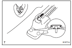
- Install the outer cover in the direction indicated by the arrow in the illustration and attach the 2 claws.
- Install front seat track bracket inner cover lh
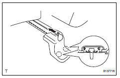
- Install the inner cover in the direction indicated by the arrow in the illustration and attach the 2 claws.
- Install front seat headrest assembly
- Connect cable to negative battery terminal
- Check srs warning light (w/ front seat side airbag)
- Check the srs warning light (see page rs-37).
- Inspect front seat assembly
- For passenger side: perform the zero point calibration and sensitivity check (see page rs-241).
- W/ seat heater system: check the seat heater operation.
- Turn the ignition switch on (ig).
- Push the seat heater switch on.
- Wait 5 minutes or more and confirm that the seat surface becomes warm.
 Front seat assembly (for power seat type lh side)
Components
...
 Removal
Hint:
Use the same procedures for the rh side and lh side.
The procedures listed below are for the rh side.
Remove front seat headrest assembly
Remove front seat assembly
Opera ...
Other materials:
Rear no. 1 Seat assembly (for lh side)
Components
...
Front wiper motor and link
Components
Removal
Disconnect cable from negative battery
terminal
Caution:
Wait at least 90 seconds after disconnecting the
cable from the negative (-) battery terminal to
prevent airbag and seat belt pretensioner activation.
Remove front wiper arm head cap
Remove the 2 c ...
Rear combination light assembly
Components
Removal
Hint:
Use the same procedures for the rh and lh sides.
The procedures listed below are for the lh side.
Disconnect cable from negative battery
terminal
Caution:
Wait at least 90 seconds after disconnecting the
cable from the negative (-) battery terminal t ...
