Toyota RAV4 (XA40) 2013-2018 Service Manual: Installation
- Install water pump assembly
- Remove any old seal packing material from the contact surface.
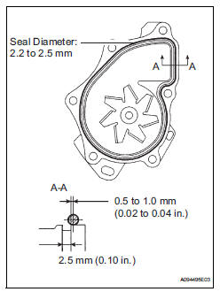
- Apply a continuous line of seal packing as shown in the illustration.
Seal packing: toyota genuine seal parking black, three bond 1207b or equivalent
Standard seal diameter: 2.2 To 2.5 Mm (0.09 To 0.10 In.)
Notice:
- Remove any oil from the contact surface.
- The parts must be set within 3 minutes after applying seal packing. Otherwise, the material must be removed and reapplied.
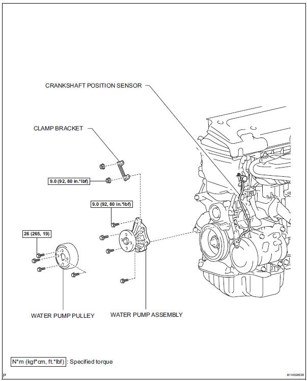
- Install the water pump and clamp bracket with the 4
bolts and 2 nuts.
Torque: 9.0 N*m (92 kgf*cm, 80 in.*Lbf)
- Install the wire of the crankshaft position sensor onto the clamp bracket.
- Install the clamp of the crankshaft position sensor onto the water pump.
- Install water pump pulley
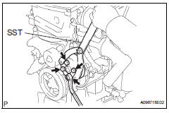
- Using sst, install the water pump pulley with the 4 bolts.
Sst 09960-10010 (09962-01000, 09963-00700) torque: 26 n*m (265 kgf*cm, 19 ft.*Lbf)
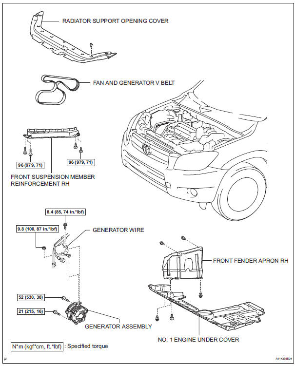
- Install generator assembly (see page ch-15)
- Install fan and generator v belt (see page em-7)
- Install front suspension member reinforcement rh (see page em-7)
- Connect cable to negative battery terminal
- Add engine coolant (see page co-6)
- Check for engine coolant leaks (see page co-1)
- Install radiator support opening cover
- Install front fender apron rh
- Install no. 1 Engine under cover
Components
 Inspection
Inspect water pump assembly
Visually check the drain hole for coolant leakage.
If leakage is found, replace the water pump
assembly.
Turn the pulley, and then check that the water ...
 Thermostat
Components
Removal
Remove no. 1 Engine under cover
Drain engine coolant (see page co-6)
Remove radiator support opening cover
Disconnect no. 2 Radiator hose
Remove water inlet
R ...
Other materials:
Precaution
If any of following conditions are met,
keep engine idling with a/c on (engine
speed at less than 2000 rpm) for at least 1
minute:
Refrigerant gas has been refilled or a/c parts have
been replaced.
A long time has elapsed since the engine was
stopped.
Notice:
If the engine s ...
Removal
(2006/01- )
Remove front wheel
Drain automatic transaxle fluid
Drain the automatic transaxle fluid for u140f (see
page ax-147).
Drain the automatic transaxle fluid for u241e (see
page ax-146).
Drain the automatic transaxle fluid for u151f (see
page ax-173).
Remove front axle hub nut ( ...
Settings display
Vehicle settings and the content
displayed on the screen can be
changed by using the meter
control switches.
â– Setting procedure
1. Press and hold to display
the cursor on the content display
area (center).
2. Press or
with the cursor
on the content display
area (center) to select
and then pre ...
