Toyota RAV4 (XA40) 2013-2018 Service Manual: Installation (2005/11-2006/01)
- Install front drive shaft assembly lh
- Coat the spline of the inboard joint shaft with gear oil.
- Using a brass bar and hammer, align the shaft splines in the drive shaft.
Notice:
- Set the snap ring with the opening side facing downwards.
- Be careful not to damage the oil seal, boot and dust cover.
- Install front drive shaft assembly rh
- Coat the spline of the inboard joint shaft with gear oil.
- Align the shaft splines and securely insert the drive shaft.
Notice:
Do not damage the oil seal.
- Squeeze the ends of the bracket hole snap ring and install it to the bearing bracket.
- Install the bearing bracket bolt torque: 32.4 N*m (330 kgf*cm, 24 ft.*Lbf)
- Connect steering knuckle with axle hub lh
- Align the shaft splines in the drive shaft to the steering knuckle with axle hub.
- Connect steering knuckle with axle hub rh
Hint:
Use the same procedures described for lh side.
- Connect front suspension lower no. 1 Arm sub-assembly lh (see page ah-10)
- Connect front suspension lower no. 1 Arm sub-assembly rh
Hint:
Use the same procedures described for lh side.
- Install front stabilizer link assembly lh (see page sp-31)
- Install front stabilizer link assembly rh
Hint:
Use the same procedures described for lh side.
- Install tie rod end sub-assembly lh (see page ps-45)
- Install tie rod end sub-assembly rh
Hint:
Use the same procedures described for lh side.
- Connect front speed sensor lh
- Connect the speed sensor (see page bc-193).
- Connect front speed sensor rh
Hint:
Use the same procedures described for the lh side.
- Install front axle hub nut (see page ah-10)
- Install front wheel torque: 103 n*m (1,050 kgf*cm, 76 ft.*Lbf)
- Add automatic transaxle fluid
- Add automatic transaxle fluid for u140f (see page ax-152).
- Add automatic transaxle fluid for u241e (see page ax-151).
- Check for automatic transaxle fluid leakage
- Inspect and adjust front wheel alignment
- Inspect and adjust front wheel alignment (see page sp-3).
 Reassembly (2006/01- )
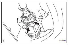
Install front drive shaft bearing (for rh)
Install the bearing bracket snap ring to the inboard
shaft.
Using sst and a press, press in the drive shaft
bearing to the inboard joint r ...
 Installation (2006/01- )
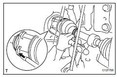
Install front drive shaft assembly lh
Coat the spline of the inboard joint shaft with gear
oil.
Align the shaft splines and tap in the drive shaft with
a brass bar and hammer.
No ...
Other materials:
Power outlets
The power outlet can be used for 12 v accessories that run on
less than 10 a.
Open the lid.
The power outlets can be used when
Vehicles without a smart key system
The engine switch is in the “acc” or “on” position.
Vehicles with a smart key system
The engine switch is in ...
Occupant classification sensor power supply circuit malfunction
Description
The occupant classification sensor power supply circuit consists of the
occupant classification ecu and
the occupant classification sensors.
Dtc b1793 is recorded when a malfunction is detected in the occupant
classification sensor power
supply circuit.
Wiring diagram
...
System description
Power door lock system description
The power door lock system locks / unlocks all
doors with a one-touch operation.
The door control switch of the power window
regulator master switch or door control switch on
passenger side sends lock / unlock request
signals to the main body ...
