Toyota RAV4 (XA40) 2013-2018 Service Manual: Key lock-in prevention function does not work properly
Description
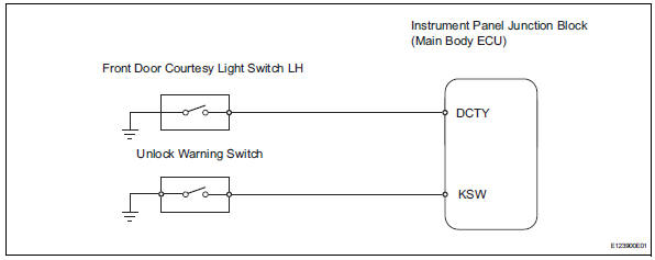
When the key is in the ignition key cylinder or the door courtesy light on signal is output to the main body ecu, performing the door lock operation with the lock switch does not lock the door.
Wiring diagram
Inspection procedure
- Read value of intelligent tester (unlock warning switch)
- Use the data list to check if the unlock warning switch is functioning properly.
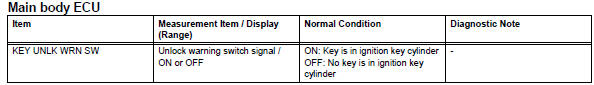
Ok: when the switch is operating, the intelligent tester should display as shown in the table.

- Read value of intelligent tester (driver side door courtesy light switch)
- Use the data list to check if the door courtesy light switch is functioning properly.
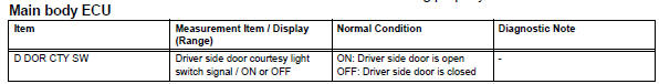
Ok: when the switch is operating, the intelligent tester should display as shown in the table.

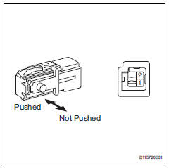
- Inspect front door courtesy light switch assembly lh
- Remove the front door courtesy light switch.
- Measure the resistance of the switch.
Standard resistance 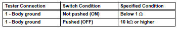

- Check wire harness (ecu - switch)
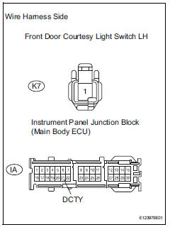
- Disconnect the k7 switch connector.
- Disconnect the ia junction block connector.
- Measure the resistance of the wire harness side connectors.
Standard resistance 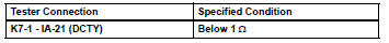

Replace instrument panel junction block (main body ecu)
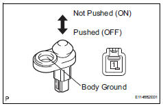
- Inspect unlock warning switch assembly
- Remove the unlock warning switch.
- Measure the resistance of the switch.
Standard resistance 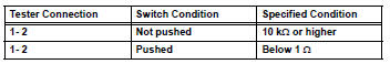

- Check wire harness (switch - ecu)
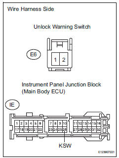
- Disconnect the e6 switch connector.
- Disconnect the ie junction block connector.
- Measure the resistance of the wire harness side connectors.
Standard resistance 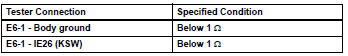

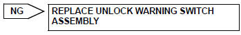
Replace instrument panel junction block (main body ecu)
 Only back door lock / unlock functions do not operate
Description
The main body ecu receives lock / unlock switch signals and activates the
door lock motor accordingly.
Wiring diagram
Inspection procedure
Inspect back door with motor lock as ...
 Key reminder warning system
Parts location
System diagram
...
Other materials:
Warning lights
Warning lights inform the driver
of malfunctions in the indicated
vehicle's systems.
Brake system warning
light*1
Brake system warning
light*1
Brake system warning
light*1
Charging system warning
light (vehicles without
12.3-inch multi-information
display)*1
Charging system warning
light (vehic ...
Problem symptoms table
Hint:
Use the table below to help determine the cause of the
problem symptom. The potential causes of the symptoms
are listed in order of probability in the "suspected area"
column of the table. Check each symptom by checking the
suspected areas in the order they are listed. Re ...
Intake air temperature sensor gradient too high
Description
The intake air temperature (iat) sensor, mounted on the mass air flow (maf)
meter, monitors the iat.
The iat sensor has a built-in thermistor with a resistance that varies according
to the temperature of the
intake air. When the iat is low, the resistance of the thermist ...
