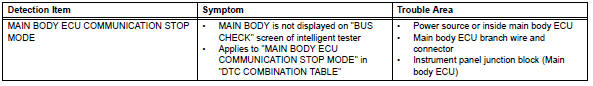
Toyota RAV4 (XA40) 2013-2018 Service Manual: Main body ecu communication stop mode
Description
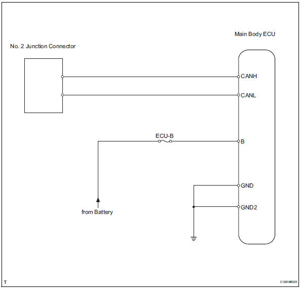
Wiring diagram
Inspection procedure
Notice:
- Turn the ignition switch off before measuring the resistances of the main wire and the branch wire.
- After the ignition switch is turned off, check that the key reminder warning system and light reminder warning system are not in operation.
- Before measuring the resistance, leave the vehicle for at least 1 minute and do not operate the ignition switch, any switches or doors. If doors need to be opened in order to check connectors, open the doors and leave them open.
Hint:
Operating the ignition switch, any switches or any doors triggers related ecu and sensor communication with the can, which causes resistance variation.
- Check can bus line for disconnection (main body ecu branch wire)
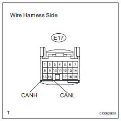
- Disconnect the e17 main body ecu connector.
- Measure the resistance of the wire harness side connector.
Standard resistance 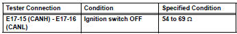

- Check wire harness (main body ecu - battery and body ground)
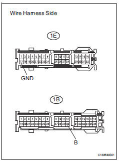
- Disconnect the 1e and 1b junction block connectors.
- Measure the resistance of the wire harness side connector.
Standard resistance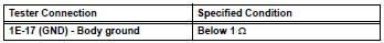
- Measure the voltage of the wire harness side connector.
Standard voltage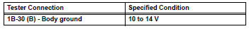

Replace instrument panel junction block (main body ecu)
 Ecm communication stop mode (2006/01- )
Description
Wiring diagram
Inspection procedure
Notice:
Turn the ignition switch off before measuring the resistances of the
main wire and branch
wire.
After the ignition swi ...
 Combination meter ecu communication stop mode
Description
Wiring diagram
Inspection procedure
Notice:
Turn the ignition switch off before measuring the resistances of the
main wire and the branch
wire.
After the ignition swi ...
Other materials:
Using the radio
Power
Volume
Adjusting the frequency
Scanning for receivable stations
Am/fm mode button
Station selectors
Seeking the frequency
Displaying text message
Setting station presets
Search for the desired stations by turning the ¢Â§tune¢escroll¢¸
knob or ...
If your vehicle needs
to be towed
If towing is necessary, we recommend having your vehicle
towed by your toyota dealer or commercial towing service,
using a wheel-lift type truck or flatbed truck.
Use a safety chain system for all towing, and abide by all state/
provincial and local laws.
2Wd models: if towing your vehicle ...
Removal
Disconnect cable from negative battery
terminal
Caution:
Wait at least 90 seconds after disconnecting the
cable from the negative (-) battery terminal to
prevent airbag and seat belt pretensioner activation.
Remove steering column cover lower
Detach the 4 claws, release the ...
