Toyota RAV4 (XA40) 2013-2018 Service Manual: Combination meter ecu communication stop mode
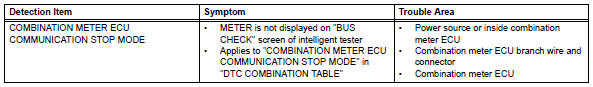
Description
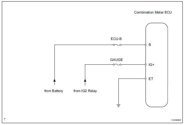
Wiring diagram
Inspection procedure
Notice:
- Turn the ignition switch off before measuring the resistances of the main wire and the branch wire.
- After the ignition switch is turned off, check that the key reminder warning system and light reminder warning system are not in operation.
- Before measuring the resistance, leave the vehicle for at least 1 minute and do not operate the ignition switch, any switches or doors. If doors need to be opened in order to check connectors, open the doors and leave them open.
Hint:
Operating the ignition switch, any switches or any doors triggers related ecu and sensor communication with the can, which causes resistance variation.
- Check wire harness (combination meter ecu - battery and body ground)
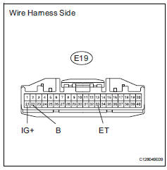
- Disconnect the e19 combination meter ecu connector.
- Measure the resistance of the wire harness side connector.
Standard resistance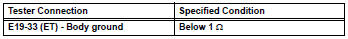
- Measure the voltage of the wire harness side connector.
Standard voltage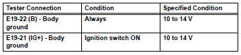

Replace combination meter ecu
 Main body ecu communication stop mode
Description
Wiring diagram
Inspection procedure
Notice:
Turn the ignition switch off before measuring the resistances of the
main wire and the branch
wire.
After the ignition sw ...
 Center airbag sensor communication stop mode
Description
Wiring diagram
Inspection procedure
Notice:
Turn the ignition switch off before measuring the resistances of the
main wire and the branch
wire.
After the ignition swi ...
Other materials:
Shift position purpose
*1: Shifting the shift lever to d allows the system to select a gear suitable
for
the driving conditions.
Setting the shift lever to d is recommended for normal driving.
*2: Selecting shift ranges using s mode restricts the upper limit of the
possible
gear ranges, controls engine bra ...
Opening/closing the back
door (vehicles with power
back door)
â– Using the wireless remote
control
Press and hold the switch.
The power back door automatically
opens/closes.
Pressing the switch while the power
back door is opening/closing stops
the operation. When the switch is
pressed and held again during the
halted operation, the back door will
perform t ...
Terminals of ecu
Skid control ecu
Hint:
*1: W/ 16-inch disc
*2: W/ downhill assist control
*3: For 2wd (w/ auto lsd)
Check skid control ecu
Disconnect the a19 ecu connector.
Measure the voltage and resistance of the wire
harness side connector.
Hint:
The voltage cannot be measured ...
