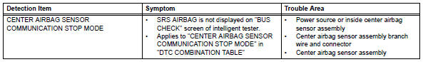
Toyota RAV4 (XA40) 2013-2018 Service Manual: Center airbag sensor communication stop mode
Description
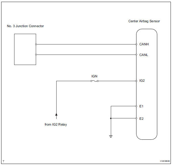
Wiring diagram
Inspection procedure
Notice:
- Turn the ignition switch off before measuring the resistances of the main wire and the branch wire.
- After the ignition switch is turned off, check that the key reminder warning system and light reminder warning system are not in operation.
- Before measuring the resistance, leave the vehicle for at least 1 minute and do not operate the ignition switch, any switches or doors. If doors need to be opened in order to check connectors, open the doors and leave them open.
Hint:
Operating the ignition switch, any switches or any doors triggers related ecu and sensor communication with the can, which causes resistance variation.
- Check can bus line for disconnection (center airbag sensor assembly branch wire)
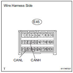
- Disconnect the e45 center airbag sensor connector.
- measure the resistance of the wire harness side connector.
Standard resistance 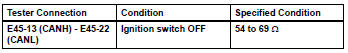

- Check wire harness (center airbag sensor assembly - battery and body ground)
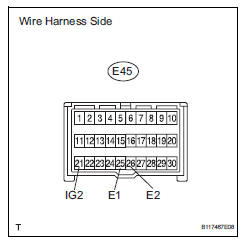
- Disconnect the e45 center airbag sensor connector.
- Measure the resistance of the wire harness side connector.
Standard resistance 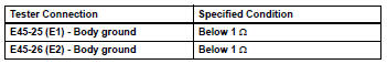
- Measure the voltage of the wire harness side connector.
Standard resistance 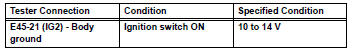

Replace center airbag sensor assembly
 Combination meter ecu communication stop mode
Description
Wiring diagram
Inspection procedure
Notice:
Turn the ignition switch off before measuring the resistances of the
main wire and the branch
wire.
After the ignition swi ...
 4Wd control ecu communication stop mode
Description
Hint:
For vehicle with 4wd only.
Wiring diagram
Inspection procedure
Notice:
Turn the ignition switch off before measuring the resistances of the
main wire and the bra ...
Other materials:
Connecting a bluetooth®
device
Up to 5 bluetooth® devices (phones (hfp) and audio players
(avp)) can be registered.
If more than 1 bluetooth® device has been registered, select
which device to connect to.
Press the “setup” button.
Select “bluetooth*”.
*: Bluetooth is a registered trademark of bluetooth sig ...
Installation
Install drive plate sub-assembly
Clean the 8 bolts and 8 bolt holes.
Apply adhesive to 2 or 3 threads of the 8 bolts.
Adhesive:
Toyota genuine adhesive 1342, three bond
1342 or equivalent
Using sst, hold the crankshaft.
Sst 09213-54015 (91651-60855), 09330-00021
Instal ...
Throttle / pedal position sensor / switch "d" circuit range / performance
Description
Hint:
Refer to dtc p2120 (see page es-282).
Monitor description
When the difference between the output voltages of vpa and vpa2 deviates from
the standard, the ecm
determines that the accelerator pedal position (app) sensor is malfunctioning.
The ecm turns on the mil
and th ...
