Toyota RAV4 (XA40) 2013-2018 Service Manual: Rear no. 2 Suspension arm
Components
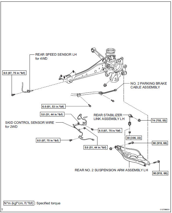
Removal
Hint:
- Use the same procedures for the rh side and lh side.
- The procedures listed below are for the lh side.
- Remove rear wheel
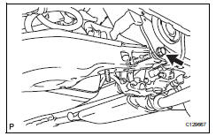
- Disconnect no. 2 Parking brake cable assembly (see page pb-8)
- Disconnect skid control sensor wire (for 2wd) (see page bc-198)
- Disconnect rear speed sensor lh (for 4wd) (see page bc-205)
- Disconnect rear stabilizer link assembly lh (see page sp-50)
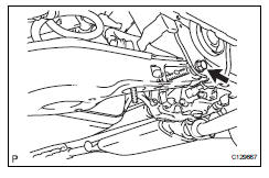
- Disconnect rear no. 2 Suspension arm assembly lh
- Loosen the bolt from the suspension member side.
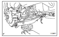
- Support the no. 2 Suspension arm lh with a jack.
Notice:
Place a wooden or rubber block between the jack and the arm.
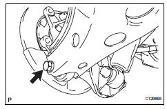
- Remove the bolt and nut from the axle carrier side.
- Slowly lower the jack, and disconnect the no. 2 Suspension arm from the axle carrier.
- Remove rear coil spring insulator upper lh (see page sp-33)
- Remove rear coil spring lh (see page sp-33)
- Remove rear coil spring insulator lower lh (see page sp-33)
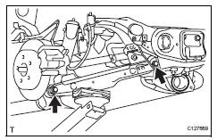
- Remove rear no. 2 Suspension arm assembly lh
- Remove the bolt, nut and suspension arm from the suspension member.
Installation
Hint:
- Use the same procedures for the rh side and lh side.
- The procedures listed below are for the lh side.
- Temporarily install rear no. 2 Suspension arm assembly lh
- Temporarily install the no. 2 Suspension arm with the bolt and nut to the suspension member.
- Install rear coil spring insulator lower lh (see page sp-34)
- Install rear coil spring lh (see page sp-34)
- Install rear coil spring insulator upper lh (see page sp-34)
- Install rear no. 2 Suspension arm assembly lh
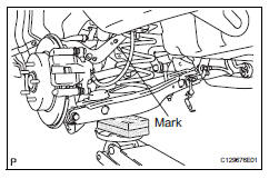
- Slowly raise the jack, and install the no. 2 Suspension arm to the axle carrier.
Notice:
Install the arm so that the coil spring's distinguishing mark is on the outer side of the vehicle.
- Install rear stabilizer link assembly lh (see page sp-52)
- Connect skid control sensor wire (for 2wd) (see page bc-198)
- Connect rear speed sensor lh (for 4wd) (see page bc-205)
- Connect no. 2 Parking brake cable assembly (see page pb-8)
- Install rear wheel
- Install the wheel.
Torque: 103 n*m (1,050 kgf*cm, 76 ft.*Lbf)
- Stabilize suspension (see page sp-37)
- Tighten rear no. 2 Suspension arm assembly lh
- Install the 2 nuts and 2 bolts.
Torque: 90 n*m (918 kgf*cm, 66 ft.*Lbf)
Notice:
Do not tighten the nuts.
- Inspect and adjust rear wheel alignment
- Inspect and adjust the rear wheel alignment (see page sp-7).
 Rear no. 1 Suspension arm
Components
Removal
Hint:
Use the same procedures for the rh side and lh side.
The procedures listed below are for the lh side.
Remove rear wheel
Remove rear no. 1 Suspension arm as ...
 Suspension & axle rear stabilizer bar
Components
...
Other materials:
Rear brake
Components
Removal
Hint:
Use the same procedures for the lh side and rh side.
The procedures listed below are for the lh side.
Remove rear wheel
Drain brake fluid
Notice:
Wash off brake fluid immediately if it comes in
contact with any painted surface.
Disconnect rea ...
Brake warning light does not come on
Wiring diagram
Refer to the brake warning light circuit (see page bc-145).
Inspection procedure
Check can communication system
Check if the can communication system dtc is output
(see page ca-34).
Result
Perform active test by intelligent tester (brake warning light)
...
Front occupant classification sensor rh collision detection
Description
Dtc b1786 is output when the occupant classification ecu receives a collision
detection signal sent by
the front occupant classification sensor rh when an accident occurs.
Dtc b1786 is also output when the front seat assembly rh is subjected to a
strong impact, even if an
a ...
