Toyota RAV4 (XA40) 2013-2018 Service Manual: Replacement
- Replace intake valve guide bush
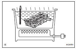
- Heat the cylinder head to 80 to 100°c (176 to 212°f).
- Place the cylinder head on wooden blocks.
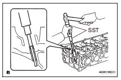
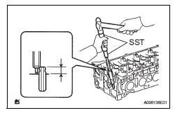
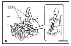
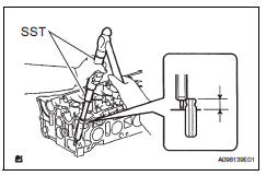
- Using sst and a hammer, tap out the guide bush.
Sst 09201-10000 (09201-01050), 09950-70010 (09951-07100)
- Heat the cylinder head to 80 to 100°c (176 to 212°f).
- Place the cylinder head on wooden blocks.
- Using a caliper gauge, measure the bush bore diameter of the cylinder head.
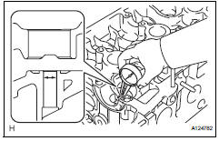
Standard diameter: 10.285 To 10.306 Mm (0.4049 To 0.4058 In.)
If the bush bore diameter of the cylinder head is greater than 10.306 Mm (0.4058 In.), Machine the bush bore to the dimension of 10.335 To 10.365 Mm (0.4068 To 0.4077 In.).
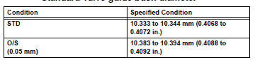
Standard valve guide bush diameter
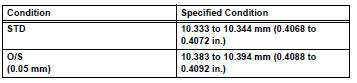
If the bushing bore diameter of the cylinder head is greater than 10.394 Mm (0.4092 In.), Replace the cylinder head.
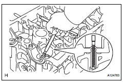
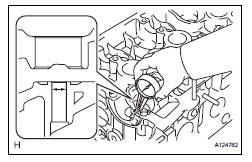
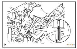
- Using sst and a hammer, tap in a new guide bush to the specified protrusion height.
Sst 09201-10000 (09201-01050), 09950-70010 (09951-07100)
Standard protrusion height: 9.6 To 10.0 Mm (0.378 To 0.394 In.)
- Using a sharp 5.5 Mm reamer, ream the valve guide bush to the standard specified clearance between the valve guide bush and valve stem.
Standard oil clearance: 0.025 To 0.060 Mm (0.0010 To 0.0024 In.)
- Replace exhaust valve guide bush
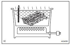
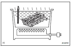
- Heat the cylinder head to 80 to 100°c (176 to 212°f).
- Place the cylinder head on wooden blocks.
- Using sst and a hammer, tap out the guide bush.
Sst 09201-10000 (09201-01050), 09950-70010 (09951-07100)
- Heat the cylinder head to 80 to 100°c (176 to 212°f).
- Place the cylinder head on wooden blocks.
- Using a caliper gauge, measure the bush bore diameter of the cylinder head.
Standard diameter: 10.285 To 10.306 Mm (0.4049 To 0.4058 In.)
If the bush bore diameter of the cylinder head is greater than 10.306 Mm (0.4058 In.), Machine the bush bore to the dimension of 10.335 To 10.365 Mm (0.4068 To 0.4077 In.).
Standard valve guide bush diameter
If the bushing bore diameter of the cylinder head is greater than 10.394 Mm (0.4092 In.), Replace the cylinder head.
- Using sst and a hammer, tap in a new guide bush to the specified protrusion height.
Sst 09201-10000 (09201-01050), 09950-70010 (09951-07100)
Standard protrusion height: 9.6 To 10.0 Mm (0.378 To 0.394 In.)
- Using a sharp 5.5 Mm reamer, ream the valve guide bush to the standard specified clearance between the valve guide bush and valve stem.
Standard oil clearance: 0.030 To 0.065 Mm (0.0012 To 0.0026 In.)
- Replace stud bolt
Notice:
If the stud bolt is deformed or threads are damaged, replace it.
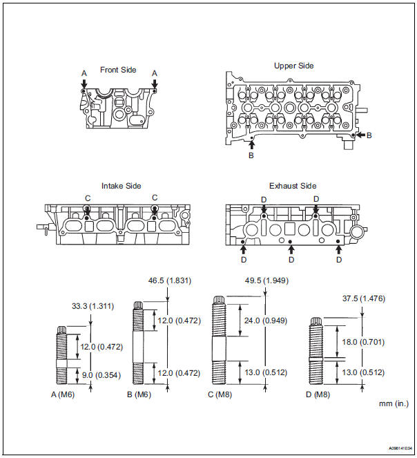
- Using e5 and e7 "torx" socket wrenches, remove the 11 stud bolts.
- Using e5 and e7 "torx" socket wrenches, install the 11 stud bolts.
- Replace ring pin
- Remove the 4 ring pins.
- Using a plastic-faced hammer, tap in 4 new ring pins to the specified protrusion height.
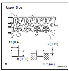
Protrusion height: 3.0 Mm (0.12 In.)
 Inspection
Inspect cylinder head for warpage
Using a precision straightedge and feeler gauge,
measure the warpage of the contact surfaces of the
cylinder block and manifolds.
Maximum warpage: ...
 Reassembly
Hint:
Thoroughly clean all parts to be assembled.
Before installing the parts, apply fresh engine oil to all
sliding and rotating surfaces.
Replace oil seals with new ones.
Install val ...
Other materials:
Inspection
Inspect engine coolant temperature sensor
Measure the resistance of the sensor.
Standard resistance
Notice:
If checking the sensor in water, be careful not to
allow water to contact the terminals. After
checking, wipe the water off the sensor.
If the result is not as specified, ...
Removal
Discharge fuel system pressure (see page
fu-9)
Disconnect cable from negative battery
terminal
Caution:
Wait at least 90 seconds after disconnecting the
cable from the negative (-) battery terminal to
prevent airbag and seat belt pretensioner activation.
Remove hood sub-assembly ( ...
Installation
Install tire pressure warning antenna and receiver
Install the receiver with the bolt.
Torque: 7.5 N*m (76 kgf*cm, 66 in.*Lbf)
Connect the connector.
Install inner roof side garnish assembly
rh (see page ir-52)
Install deck trim side panel assembly rh
(w/o rear no. 2 S ...
