Toyota RAV4 (XA40) 2013-2018 Service Manual: Solar sensor circuit (driver side)
![]()
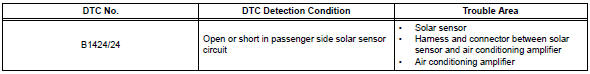
Description
The solar sensor, which is installed on the upper side of the instrument panel, detects sunlight and controls the air conditioning auto mode. The output voltage from the solar sensor varies in accordance with the amount of sunlight. When the sunlight increases, the output voltage increases. As the sunlight decreases, the output voltage decreases.
The air conditioning amplifier detects changes in the output voltage from the solar sensor.
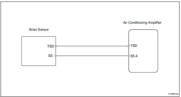
Wiring diagram
Inspection procedure
- Read value of intelligent tester (solar sensor d side)
- Connect the intelligent tester (with can vim) to the dlc3.
- Turn the ignition switch on and turn the intelligent tester main switch on.
- Select the item below in the data list, and read the value displayed on the intelligent tester.
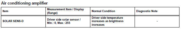
Ok: the display is as specified in the normal condition column.

- Inspect solar sensor
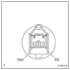
- Remove the solar sensor.
- Measure the resistance of the sensor.
- Connect the ohmmeter's positive (+) lead to terminal 1 and the negative (-) lead to terminal 3 of the solar sensor.
Standard resistance 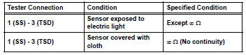
Notice:
The connection procedure for using a digital tester such as an electrical tester is shown above. When using an analog tester, connect the positive (+) lead to terminal 3 and the negative (-) lead to terminal 1 of the solar sensor.
Hint:
- As the inspection light is moved away from the sensor, the voltage decreases.
- Use an incandescent light for the inspection. Position it about 30 cm (11.8 In.) From the solar sensor.

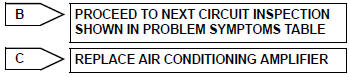
- Check wire harness (solar sensor - air conditioning amplifier)
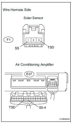
- Disconnect the f1 sensor connector.
- Disconnect the e37 amplifier connector.
- Measure the resistance of the wire harness side connectors.
Standard resistance 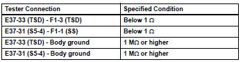

Replace air conditioning amplifier
 Pressure sensor circuit
Description
This dtc is output when the refrigerant pressure is either extremely low
(0.19 Mpa [2.0 Kgf/cm2, 28 psi]
or less) or extremely high (3.14 Mpa [32.0 Kgf/cm2, 455 psi] or more). The ...
 Air mix damper control servo motor circuit (passenger side)
Description
The air mix damper servo sends pulse signals to indicate the damper position
to the air conditioning
amplifier. The air conditioning amplifier activates the motor (normal or
reve ...
Other materials:
Brake switch "b" circuit high
Description
The purpose of this circuit is to prevent the engine from stalling while
driving in the lock-up condition when
the brakes are suddenly applied.
When the brake pedal is depressed, this switch sends a signal to the ecm. Then
the ecm cancels the
operation of the lock-up clutch ...
How to proceed with troubleshooting
Hint:
Use these procedures to troubleshoot the seat belt
warning system.
*: Use the intelligent tester.
Vehicle brought to workshop
Inspect battery voltage
Standard voltage:
11 to 14 v
If the voltage is below 11 v, recharge or replace the battery
before proceeding.
...
System description
General
In conjunction with an impact absorbing structure for
a frontal collision, the srs (supplemental restraint
system) driver airbag, front passenger airbag and
driver side knee airbag were designed to
supplement seat belts in the event of a frontal
collision in order to help ...
