Toyota RAV4 (XA40) 2013-2018 Service Manual: System description
- General
- In conjunction with an impact absorbing structure for
a frontal collision, the srs (supplemental restraint
system) driver airbag, front passenger airbag and
driver side knee airbag were designed to
supplement seat belts in the event of a frontal
collision in order to help reduce shock to the head,
chest and knee of the driver and front passenger.
This system is a 3-sensor type airbag system to detect the impact during a frontal collision using the center airbag sensor and front airbag sensors. It also operates the airbag system and seat belt pretensioner.
- In order to detect the extent of the collision during the initial stages of the collision in further detail, the front airbag sensors have been changed from mechanical type to electrical type deceleration sensors. Accordingly, the deployment of the driver airbag and front passenger airbag is controlled in two stages according to the severity of the impact.
- In conjunction with an impact absorbing structure for a side collision, the side airbag and curtain shield airbag were designed to help reduce shock to the driver and front passenger in the event of a side collision.
- A curtain shield airbag that helps reduce shock to the front and rear seat occupants with a single curtain shield airbag has been adopted. In conjunction with this system, the side airbag sensors have been installed at the bottom of the center pillars and rear airbag sensors have been installed at the bottom of the rear pillars.
- In this system, a front side collision is detected by the side airbag sensor in order to simultaneously deploy the side airbag. A rear side collision is detected by the rear airbag sensor and the center airbag sensor in order to deploy the side airbag and curtain shield airbag.
- The center airbag sensor sends the airbag deployment signal to the ecm through the can (controller area network) to operate the fuel pump control.
- Construction and operation
- Front airbag sensor
- The front airbag sensors are installed on the right and left radiator supports.
- The front airbag sensor consists of the deceleration sensor.
- The deceleration sensor is built into the front airbag sensor, and the distortion that is created in the sensor is converted into an electric signal based on the vehicle deceleration rate during a frontal collision. Accordingly, the extent of the initial collision can be detected in detail.
- Side airbag sensor
- The side airbag sensors are installed on the bottom of the right and left center pillars.
- The side airbag sensor consists of the deceleration sensor and ignition control circuit.
- The deceleration sensor is built into the side airbag sensor, and the distortion that is created in the sensor is converted into an electric signal based on the vehicle deceleration rate during a front side collision. Accordingly, the extent of the initial collision can be detected in detail.
- Rear airbag sensor
- The rear airbag sensors are installed on the right and left rear pillars.
- The rear airbag sensor consists of the deceleration sensor and ignition control circuit.
- The deceleration sensor is built into the rear airbag sensor, and the distortion that is created in the sensor is converted into an electric signal based on the vehicle deceleration rate during a rear side collision. Accordingly, the extent of the initial collision can be detected in detail.
- Center airbag sensor
- General
- The center airbag sensor is installed on the center floor under the console box.
- The center airbag sensor consists of the deceleration sensor, safing sensor, electronic safing sensor, ignition control circuit and diagnostic circuit.
- The center airbag sensor receives signals from the deceleration sensor and safing sensor built into the center airbag sensor and front airbag sensor. Then the center airbag sensor determines whether or not the driver airbag, front passenger airbag, driver side knee airbag and seat belt pretensioner should be activated, and diagnoses system malfunctions.
- The center airbag sensor causes the side airbag and the curtain shield airbag to deploy when receiving signals from the side and rear airbag sensor.
- The center airbag sensor receives signals from the deceleration sensor and the electronic safing sensor built into the center airbag sensor and the rear airbag sensor, and determines whether or not the side airbag and curtain shield airbag should be activated, and diagnoses system malfunctions.
- The center airbag sensor sends the airbag deployment signal to ecm through the can to operate the fuel pump control.
- Deceleration sensor and ignition control circuit
- The deceleration sensor is built into the center airbag sensor.
- The ignition control circuit performs calculations based on the signal output from the deceleration sensors of the center airbag sensor and front airbag sensor. If the calculated values are greater than the specified values, it activates the deployment operation.
- Safing sensor
The safing sensor is built into the center airbag sensor. During a frontal collision, the sensor turns on and outputs an on signal to the center airbag sensor if a deceleration rate greater than the specified value is applied to the safing sensor.
- Electronic safing sensor
The electronic safing sensor is built into the center airbag sensor. During a side collision, the sensor turns on and outputs an on signal to the center airbag sensor if a deceleration rate greater than the specified value is applied to the electronic safing sensor.
- Back-up power source
The back-up power source consists of a power supply capacitor and a dc-dc converter. When the power system does not function during a collision, the power supply capacitor discharges and supplies electric power to the system. The dc-dc converter operates as a boosting transformer when the battery voltage falls below a predetermined level.
- Diagnostic circuit
This circuit constantly diagnoses system malfunctions. When a malfunction is detected, it lights up the srs warning light on the telltale light to inform the driver.
- Memory circuit
When a malfunction is detected in the diagnostic circuit, it is coded and stored in the memory circuit.
- Srs warning light
- The srs warning light is located on the telltale light. It comes on to inform the driver of system trouble when a malfunction is detected in the self-diagnosis of the center airbag sensor. Under normal operating conditions when the ignition switch is turned on, it comes on for approximately 6 seconds and then goes off.
- Deployment condition
When the vehicle collides and the shock is greater than the specified value, the srs is activated automatically.
The center airbag sensor includes the safing sensor and deceleration sensor. The safing sensor was designed to be turned on at a smaller deceleration rate than the deceleration sensor.
- The center airbag sensor determines whether or not deployment is necessary based on signals from the deceleration sensor and the front airbag sensor*. If the safing sensor turns on simultaneously, current flows to the squibs to deploy the srs as shown in the illustration below.
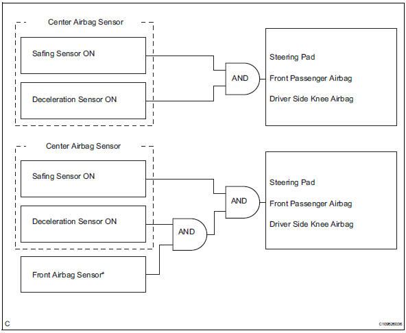
Hint:
* : In case of a frontal collision, the ignition signal could be output with the deceleration sensor on signal even without a signal from the front airbag sensor.
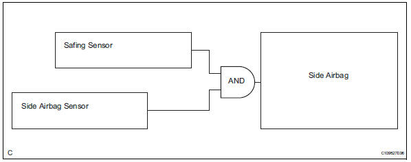
- The center airbag sensor determines whether or not deployment is necessary based on signals from the side airbag sensor. If the safing sensor turns on simultaneously, current flows to the squib to deploy the srs as shown in the illustration below.
- The center airbag sensor determines whether or not deployment is necessary based on signals from the rear airbag sensor. If the safing sensor turns on simultaneously, current flows to the squib to deploy the srs as shown in the illustration below*.
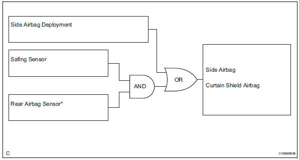
Hint:
*: If the side airbag deploys, the curtain shield airbag will also deploy, regardless of whether the signal is output from the rear airbag sensor.
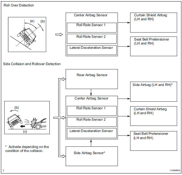
- The center airbag sensor contains a roll rate sensor and roll rate sensor (that determine the inclination angle the vehicle) and a lateral deceleration sensor (that determine the lateral force that is applied to the vehicle). These sensors detect the vehicle's roll angle (a), rotational speed (b), and lateral acceleration speed (c). Based on the information obtained from sensors, the airbag sensor makes an overall judgment of the vehicle's roll angle (a), rotational speed (b), and lateral acceleration speed (c). If the airbag sensor determines that the vehicle has rolled over due to cause other than the side collision, it deploys the right and left curtain shield airbag and the front right and left seat belt pretensioner.
 Parts location
System diagram
...
 How to proceed with troubleshooting
Hint:
Use these procedures to troubleshoot the supplemental
restraint system.
*: Use the intelligent tester.
Vehicle brought to workshop
Inspect battery voltage*
Standard volt ...
Other materials:
Inspection
Inspect starter assembly
Notice:
These tests must be performed within 3 to 5 seconds
to avoid burning out the coil.
Perform the pull-in test.
Disconnect the lead wire from terminal c.
Connect the battery to the magnetic switch as
shown in the illustration. Check that the clutch ...
Intake air temperature circuit malfunction
Description
The intake air temperature (iat) sensor, mounted on the mass air flow (maf)
meter, monitors the iat.
The iat sensor has a built-in thermistor with a resistance that varies according
to the temperature of the
intake air. When the iat is low, the resistance of the thermist ...
BluetoothÂź audio/phone
BluetoothÂź audio
The bluetoothÂź audio system enables you to enjoy music played on
a portable digital audio player (portable player) from the vehicle
speakers via wireless communication.
This audio system supports bluetoothÂź, a wireless data system
capable of playing portable audio music wi ...
