Toyota RAV4 (XA40) 2013-2018 Service Manual: Yaw rate sensor communication stop mode
Description
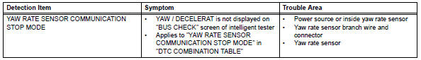
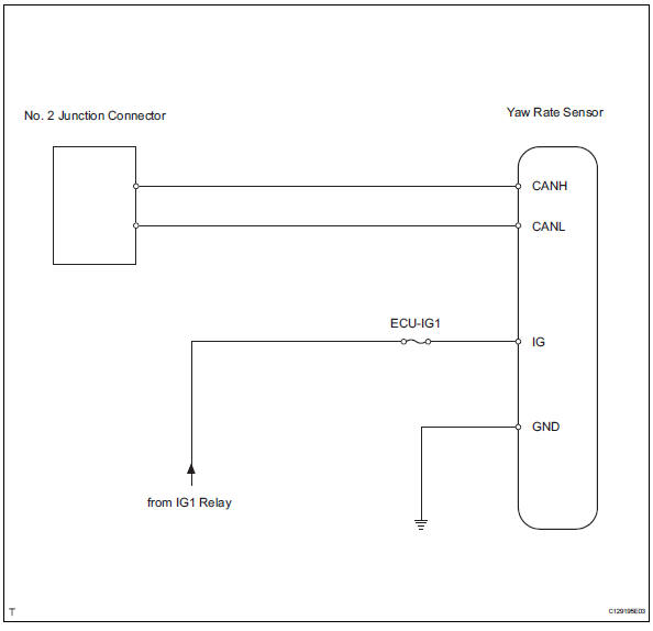
Wiring diagram
Inspection procedure
Notice:
- Turn the ignition switch off before measuring the resistances of the main wire and the branch wire.
- After the ignition switch is turned off, check that the key reminder warning system and light reminder warning system are not in operation.
- Before measuring the resistance, leave the vehicle for at least 1 minute and do not operate the ignition switch, any switches or doors. If doors need to be opened in order to check connectors, open the doors and leave them open.
Hint:
Operating the ignition switch, any switches or any doors triggers related ecu and sensor communication with the can, which causes resistance variation.
- Check can bus line for disconnection (yaw rate sensor branch wire)
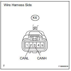
- Disconnect the k6 yaw rate sensor connector.
- Measure the resistance of the wire harness side connector.
Standard resistance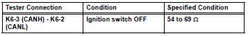

- Check wire harness (yaw rate sensor - battery and body ground)
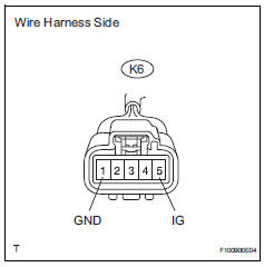
- Disconnect the k6 yaw rate sensor connector.
- Measure the resistance of the wire harness side connector.
Standard resistance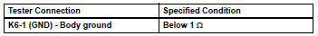
- Measure the voltage of the wire harness side connector.
Standard voltage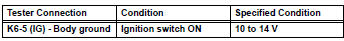

Replace yaw rate sensor
 Steering angle sensor communication stop mode
Description
Wiring diagram
Inspection procedure
Notice:
Turn the ignition switch off before measuring the resistances of the
main wire and the branch
wire.
After the ignition swi ...
 Ecm communication stop mode (2005/11-2006/01)
Description
Wiring diagram
Inspection procedure
Notice:
Turn the ignition switch off before measuring the resistances of the
main wire and the branch
wire.
After the ignition swi ...
Other materials:
Checking the battery
Check the battery as follows.
â– Battery exterior
Make sure that the battery terminals
are not corroded and that
there are no loose connections,
cracks, or loose clamps.
Terminals
Hold-down clamp
â– Before recharging
When recharging, the battery produces
hydrogen gas which is flammable
and exp ...
How to proceed with troubleshooting (2006/01- )
Hint:
Use these procedures to troubleshoot the air conditioning
system
*: Use the intelligent tester.
Vehicle brought to workshop
Customer problem analysis and symptom check
Inspect battery voltage
Standard voltage:
11 to 14 v
If the voltage is below 11 v, rechar ...
Removal
Hint:
Use the same procedures for the rh side and lh side.
The procedures listed below are for the lh side.
Disconnect cable from negative battery
terminal
Caution:
Wait at least 90 seconds after disconnecting the
cable from the negative (-) battery terminal to
prevent airbag and ...
