Toyota RAV4 (XA40) 2013-2018 Service Manual: Air mix control servo motor (for automatic air conditioning system)
Components
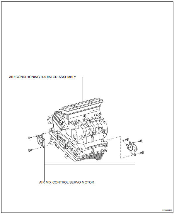
Removal
- Remove air conditioning unit
- Remove the air conditioning radiator (see page ac- 185).
- Remove air mix control servo motor (see page ac-191)
Inspection
- Inspect air mix control servo motor
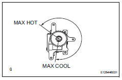
- Inspect the servo motor operation.
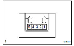
- Connect the positive (+) lead from the battery to terminal 4 and negative (-) lead to terminal 5, and then check that the lever turns to the "max hot" position smoothly.
- Connect the positive (+) lead from the battery
to terminal 5 and negative (-) lead to terminal 4,
and then check that the lever turns to the "max
cool" position smoothly.
If the operation is not as specified, replace the air mix control servo motor.
 Air inlet control servo motor
Components
Removal
Remove blower assembly
Remove the blower (see page ac-203).
Remove air inlet control servo motor (see
page ac-210)
Inspection
Inspect air inlet control ...
 Compressor and pulley (for 2az-fe)
Components
Removal
Discharge refrigerant from
refrigeration system (see page ac-172)
Disconnect cable from negative battery
terminal
Caution:
Wait at least 90 seconds after disconne ...
Other materials:
Front brake
Components
Removal
Hint:
Use the same procedures for the lh side and rh side.
The procedures listed below are for the lh side.
Remove front wheel
Drain brake fluid
Notice:
Wash off brake fluid immediately if it comes in
contact with any painted surface.
Disconnec ...
Components
(2006/01- )
...
Lumbar support adjuster assembly
Inspection
Inspect lumbar support adjuster assembl
Check operation of the lumbar support adjuster.
Check if the lumbar support adjuster moves
smoothly when the battery is connected to the
lumbar support adjuster motor connector
terminals.
Ok
If the result is not as spec ...
