Toyota RAV4 (XA40) 2013-2018 Service Manual: Brake booster
Installation (2005/11-2006/01)
- Install check valve grommet
- Install the grommet to the booster.
- Install brake vacuum check valve assembly
- Install the check valve to the grommet.
- Install brake booster gasket
- Install a new gasket to the booster.
- Install brake master cylinder push rod clevis
- Install the push rod clevis to the booster.
- Temporarily tighten the push rod clevis lock nut.
Hint:
The push rod clevis lock nut will be tightened to a torque specification in the "check and adjust brake pedal height" procedures.
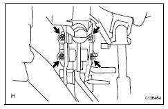
- Install brake booster assembly
- Install the booster with the 4 nuts.
Torque: 12.7 N*m (130 kgf*cm, 9 ft.*Lbf)
- Install push rod pin
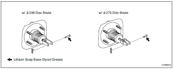
- Apply lithium soap base glycol grease to the push rod pin.
- Install the push rod pin to the push rod clevis.
Notice:
The push rod pin must be installed as shown in the illustration.
- Install the clip to the push rod pin.
Notice:
The clip must be installed as shown in the illustration.
- Check and adjust brake booster push rod (see page br-24)
- Connect vacuum hose
- Connect the vacuum hose to the check valve.
- Install brake master cylinder subassembly (see page br-25)
- Install abs and traction actuator assembly with bracket (see page bc-186)
- Connect brake lines (see page bc-187)
- Fill reservoir with brake fluid (see page br- 6)
- Bleed air from brake master cylinder (see page br-7)
- Bleed air from brake line (see page br-7)
- Bleed air from abs and traction actuator assembly (see page br-8)
- Check and adjust brake pedal height (see page br-13)
- Check brake pedal free play (see page br- 14)
- Check brake pedal reserve distance (see page br-14)
- Check brake fluid level in reservoir (see page br-6)
- Check for brake fluid leakage
- Install air cleaner case sub-assembly
- Install the air cleaner case (see page em-105).
Hint:
Refer to the procedures from the installation of the air cleaner case up until the installation of the purge vsv.
Installation (2006/01- )
- Install check valve grommet
- Install the grommet to the booster.
- Install brake vacuum check valve assembly
- Install the check valve to the grommet.
- Install brake booster gasket
- Install a new gasket to the booster.
- Install brake master cylinder push rod clevis
- Install the push rod clevis to the booster.
- Temporarily tighten the push rod clevis lock nut.
Hint:
The push rod clevis lock nut will be tightened to a torque specification in the "check and adjust brake pedal height" procedures.
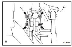
- Install brake booster assembly
- Install the booster with the 4 nuts.
Torque: 12.7 N*m (130 kgf*cm, 9 ft.*Lbf)
- Install push rod pin
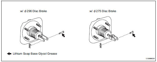
- Apply lithium soap base glycol grease to the push rod pin.
- Install the push rod pin to the push rod clevis.
Notice:
The push rod pin must be installed as shown in the illustration.
- Install the clip to the push rod pin.
Notice:
The clip must be installed as shown in the illustration.
- Check and adjust brake booster push rod (see page br-24)
- Connect vacuum hose
- Connect the vacuum hose to the check valve.
- Install brake master cylinder subassembly (see page br-26)
- Install abs and traction actuator assembly with bracket (see page bc-187)
- Connect brake lines (see page bc-188)
- Fill reservoir with brake fluid (see page br- 6)
- Bleed air from brake master cylinder (see page br-7)
- Bleed air from brake line (see page br-7)
- Bleed air from abs and traction actuator assembly (see page br-8)
- Check and adjust brake pedal height (see page br-15)
- Check brake pedal free play (see page br- 15)
- Check brake pedal reserve distance (see page br-16)
- Check brake fluid level in reservoir (see page br-6)
- Check for brake fluid leakage
- Install air cleaner case sub-assembly (for 2az-fe)
- Install the air cleaner case (see page em-105).
Hint:
Refer to the procedures from the installation of the air cleaner case up until the installation of the purge vsv.
- Install air cleaner case (for 2gr-fe)
- Install the air cleaner case (see page em-31).
Hint:
Refer to the procedures from the installation of the air cleaner case up until the installation of the air cleaner cap sub-assembly.
 Brake master cylinder
Components
On-vehicle inspection
Check brake fluid level warning switch
Remove the reservoir filler cap and strainer.
Disconnect the brake fluid level warning switch
connector.
...
 Front brake
Components
Removal
Hint:
Use the same procedures for the lh side and rh side.
The procedures listed below are for the lh side.
Remove front wheel
Drain brake fluid
Notic ...
Other materials:
Back door
The back door can be locked/unlocked and opened/closed by
the following procedures.
Locking and unlocking the back door
Door lock switch
Entry function (if equipped)
Wireless remote control
Opening/closing the back door from inside the vehicle (vehicles
with a power back door)
Press a ...
Wheels
If a wheel is bent, cracked or heavily corroded, it should be
replaced. Otherwise, the tire may separate from the wheel or
cause a loss of handling control.
Wheel selection
When replacing wheels, care should be taken to ensure that they are
equivalent to those removed in load capacity, diameter ...
Can bus line
Description
When any dtc for the can communication system is output, first measure the
resistance between the
terminals of the dlc3 to specify the trouble area, and check that there is not a
short in the can main wire,
between the main wire, to +b, or to gnd.
Wiring diagram
Inspecti ...
