Toyota RAV4 (XA40) 2013-2018 Service Manual: Brake pedal
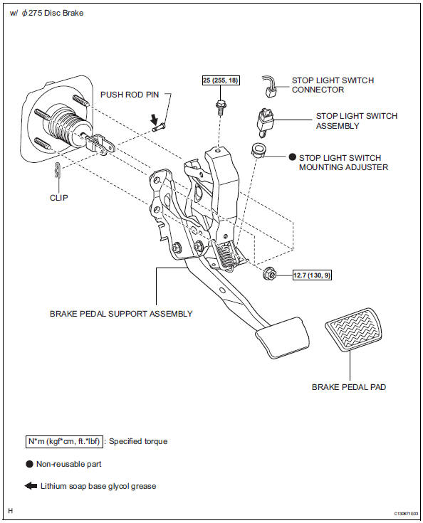
Components
Removal
- Disconnect cable from negative battery terminal
Caution:
Wait at least 90 seconds after disconnecting the cable from the negative (-) battery terminal to prevent airbag and seat belt pretensioner activation.
- Remove instrument panel sub-assembly
- Remove the instrument panel (see page ip-4).
- Disconnect connectors
- Disconnect the stop light switch connector.
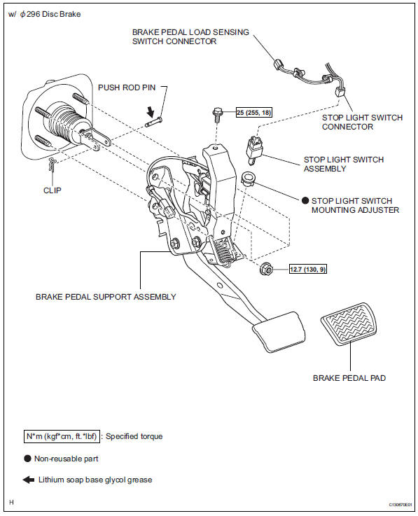
- W/
 296 disc brake:
disconnect the brake pedal load sensing switch connector.
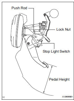
- Remove stop light switch assembly
- Turn the switch counterclockwise and remove it.
- Remove push rod pin
- Remove the clip from the push rod pin.
- Remove the push rod pin from the push rod clevis.
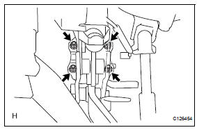
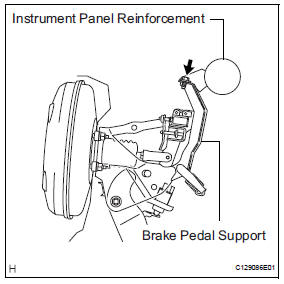
- Remove brake pedal support assembly
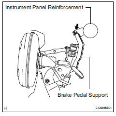
- Remove the bolt from the support.
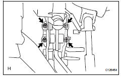
- Remove the 4 nuts and support.
Disassembly
- Remove stop light switch mounting adjuster
- Remove the adjuster from the support
- Remove brake pedal pad
Inspection
- Inspect stop light switch assembly
- Measure the resistance of the switch.
Standard resistance 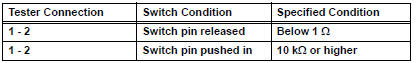
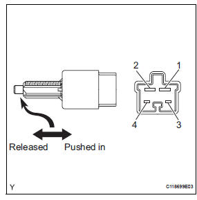
If the result is not as specified, replace the stop light switch assembly.
Adjustment (2005/11-2006/01)
- Check and adjust brake pedal height
- Check the pedal height.
Standard pedal height from dash panel: 184.2 To 194.2 Mm (7.252 To 7.646 In
.)
- Adjust the pedal height.
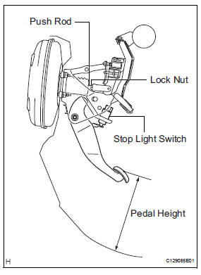
- Disconnect the connector from the stop light switch.
- Remove the switch.
- Loosen the push rod clevis lock nut.
- Adjust the pedal height by turning the push rod.
- Tighten the lock nut.
Torque: 26 n*m (265 kgf*cm, 19 ft.*Lbf)
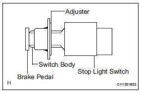
- Insert the switch into the adjuster until the switch body touches the pedal.
Notice:
Do not depress the pedal.
- Turn the switch a quarter turn clockwise.
Torque: 1.5 N*m (15 kgf*cm, 13 in.*Lbf) or less
Notice:
Do not depress the pedal.
- Connect the connector to the switch.
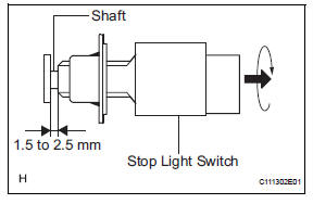
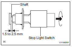
- Check the switch clearance.
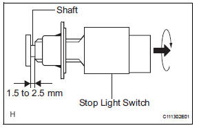
Standard stop light switch clearance: 1.5 To 2.5 Mm (0.059 To 0.098 In.)
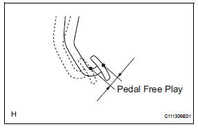
- Check brake pedal free play
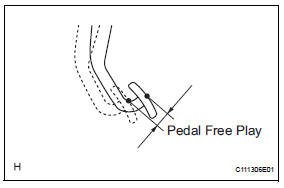
- Stop the engine. Depress the pedal several times until there is no vacuum in the booster. Then release the pedal.
- Depress the pedal until resistance is felt.
- Check the pedal's free play by measuring the distance between the position in the previous step and the pedal's released position.
Standard pedal free play: 1.0 To 6.0 Mm (0.039 To 0.236 In.)
If the free play is not as specified, check the switch clearance in the next step.
If the free play is as specified, proceed to the "check brake pedal reserve distance" procedure.
- Check the switch clearance.
Standard stop light switch clearance: 1.5 To 2.5 Mm (0.059 To 0.098 In.)
If the clearance is not as specified, reinstall the switch and recheck the pedal's free play.
If the clearance is as specified, troubleshoot the brake system and proceed to the "check brake pedal reserve distance" procedure.
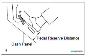
- Check brake pedal reserve distance
- Release the parking brake lever. Start the engine.
- Depress the pedal and check the pedal reserve distance.
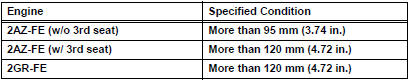
Standard pedal reserve distance 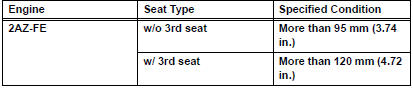
If the distance is not as specified, troubleshoot the brake system.
Adjustment (2006/01- )
- Check and adjust brake pedal height
- Check the pedal height.
Standard pedal height from dash panel: 184.2 To 194.2 Mm (7.252 To 7.646 In.)
- Adjust the pedal height.
- Disconnect the connector from the stop light switch.
- Remove the switch.
- Loosen the push rod clevis lock nut.
- Adjust the pedal height by turning the push rod.
- Tighten the lock nut.
Torque: 26 n*m (265 kgf*cm, 19 ft.*Lbf)
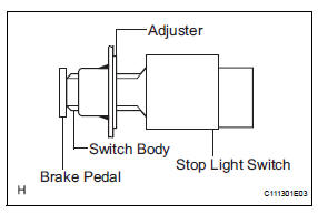
- Insert the switch into the adjuster until the switch body touches the pedal.
Notice:
Do not depress the pedal.
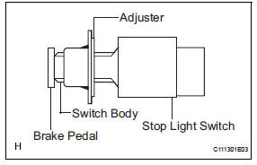
- Turn the switch a quarter turn clockwise.
Torque: 1.5 N*m (15 kgf*cm, 13 in.*Lbf) or less
Notice:
Do not depress the pedal.
- Connect the connector to the switch.
- Check the switch clearance.
Standard stop light switch clearance: 1.5 To 2.5 Mm (0.059 To 0.098 In.)
- Check brake pedal free play
- Stop the engine. Depress the pedal several times until there is no vacuum in the booster. Then release the pedal.
- Depress the pedal until resistance is felt.
- Check the pedal's free play by measuring the distance between the position in the previous step and the pedal's released position.
Standard pedal free play: 1.0 To 6.0 Mm (0.039 To 0.236 In.)
If the free play is not as specified, check the switch clearance in the next step.
If the free play is as specified, proceed to the "check brake pedal reserve distance" procedure.
- Check the switch clearance.
Standard stop light switch clearance: 1.5 To 2.5 Mm (0.059 To 0.098 In.)
If the clearance is not as specified, reinstall the switch and recheck the pedal's free play.
If the clearance is as specified, troubleshoot the brake system and proceed to the "check brake pedal reserve distance" procedure.
- Check brake pedal reserve distance
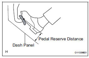
- Release the parking brake lever. Start the engine.
- Depress the pedal and check the pedal reserve distance.
- Depress the pedal with a force of 490 n (50 kgf, 110 lbf).
- Measure the distance between the pedal and dash panel shown in the illustration.
Standard pedal reserve distance
If the distance is not as specified, troubleshoot the brake system.
Reassembly
- Install brake pedal pad
- Install the pad to the pedal.
- Install stop light switch mounting adjuster
- Install a new adjuster to the support.
Installation
- Install brake pedal support assembly
- Install the support with the 4 nuts.
Torque: 12.7 N*m (130 kgf*cm, 9 ft.*Lbf)
- Install the bolt to the support.
Torque: 25 n*m (255 kgf*cm, 18 ft.*Lbf)
- Install push rod pin
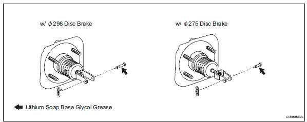
- Apply lithium soap base glycol grease to the push rod pin.
- Install the push rod pin to the push rod clevis.
Notice:
The push rod pin must be installed as shown in the illustration.
- Install the clip to the push rod pin.
Notice:
The clip must be installed as shown in the illustration.
- Install stop light switch assembly
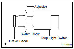
- Insert the switch into the adjuster until the switch body touches the pedal.
Notice:
Do not depress the pedal.
- Turn the switch a quarter turn clockwise.
Torque: 1.5 N*m (15 kgf*cm, 13 in.*Lbf) or less
Notice:
Do not depress the pedal.
- Check the switch clearance.
Standard stop light switch clearance: 1.5 To 2.5 Mm (0.059 To 0.098 In.)
- Connect connectors
- W/ ö296 disc brake:
Connect the brake pedal load sensing switch connector.
- Connect the stop light switch connector.
- Check and adjust brake pedal height (see page br-13)
- Check brake pedal free play (see page br- 14)
- Check brake pedal reserve distance (see page br-14)
- Install instrument panel sub-assembly
- Install the instrument panel (see page ip-9).
- Connect cable to negative battery terminal
 Bleeding
Hint:
If any work is performed on the brake system or if air in the
brake lines is suspected, bleed air from the brake system.
Notice:
Wash off brake fluid immediately if it comes in contact
with ...
 Brake master cylinder
Components
On-vehicle inspection
Check brake fluid level warning switch
Remove the reservoir filler cap and strainer.
Disconnect the brake fluid level warning switch
connector.
...
Other materials:
Reassembly (2005/11-2006/01)
Install drive shaft bearing case subassembly
Using sst and a press, press in the drive shaft
bearing case to the inboard joint rh.
Sst 09527-10011, 09710-04081
Notice:
The bearing should be installed completely.
Using a snap ring expander, install a new drive shaft
hole ...
System description
General
The air conditioning system has the following
features:
In accordance with the temperature set using the
temperature control switch, the air conditioning
amplifier determines the outlet temperature
based on the input signals from various sensors.
In addition, corre ...
Lda
(lane departure alert)
Summary of function
While driving on a road that has lane markers, this system recognizes
the lane markers using a camera as a sensor to alert the driver when
the vehicle deviates from its lane.
If the system judges that the vehicle may deviate from its lane, it alerts
the driver using beepin ...
