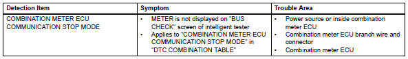
Toyota RAV4 (XA40) 2013-2018 Service Manual: Combination meter ecu communication stop mode
Description
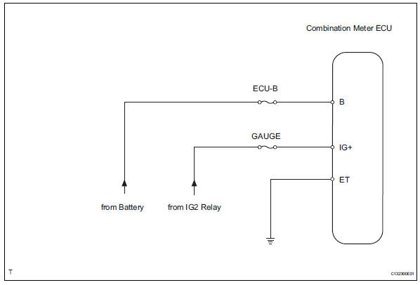
Wiring diagram
Inspection procedure
Notice:
- Turn the ignition switch off before measuring the resistances of the main wire and the branch wire.
- After the ignition switch is turned off, check that the key reminder warning system and light reminder warning system are not in operation.
- Before measuring the resistance, leave the vehicle for at least 1 minute and do not operate the ignition switch, any switches or doors. If doors need to be opened in order to check connectors, open the doors and leave them open.
Hint:
Operating the ignition switch, any switches or any doors triggers related ecu and sensor communication with the can, which causes resistance variation.
- Check wire harness (combination meter ecu - battery and body ground)
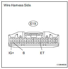
- Disconnect the e19 combination meter ecu connector.
- Measure the resistance of the wire harness side connector.
Standard resistance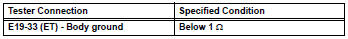
- Measure the voltage of the wire harness side connector.
Standard voltage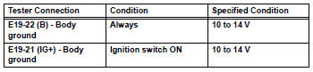

Replace combination meter ecu
 Main body ecu communication stop mode
Description
Wiring diagram
Inspection procedure
Notice:
Turn the ignition switch off before measuring the resistances of the
main wire and the branch
wire.
After the ignition sw ...
 Center airbag sensor communication stop mode
Description
Wiring diagram
Inspection procedure
Notice:
Turn the ignition switch off before measuring the resistances of the
main wire and the branch
wire.
After the ignition swi ...
Other materials:
Shift lock system
Parts location
System diagram
On-vehicle inspection
Check shift lock operation
Move the shift lever to p.
Turn the ignition switch off.
Check that the shift lever cannot be moved to any
position other than p.
Turn the ignition switch on, depress the brake
pedal and chec ...
Circuit inspection
A description of the main areas of each circuit inspection
is below.
Item
Description
description
The major role, operation of the circuit and its component parts are
explained.
Dtc no., Dtc detection condition, trouble area
Indicates the diagnostic trouble cod ...
Fuel tank cap
Inspection
Inspect fuel tank cap assembly
Visually check that the cap and gasket are not
deformed or damaged.
If the result is not as specified, replace the cap
assembly or gasket.
Remove the gasket from the exhaust manifold.
...
