Toyota RAV4 (XA40) 2013-2018 Service Manual: Center airbag sensor communication stop mode
Description
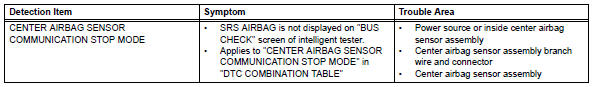
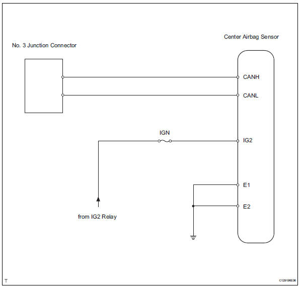
Wiring diagram
Inspection procedure
Notice:
- Turn the ignition switch off before measuring the resistances of the main wire and the branch wire.
- After the ignition switch is turned off, check that the key reminder warning system and light reminder warning system are not in operation.
- Before measuring the resistance, leave the vehicle for at least 1 minute and do not operate the ignition switch, any switches or doors. If doors need to be opened in order to check connectors, open the doors and leave them open.
Hint:
Operating the ignition switch, any switches or any doors triggers related ecu and sensor communication with the can, which causes resistance variation.
- Check can bus line for disconnection (center airbag sensor assembly branch wire)
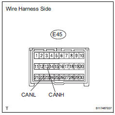
- Disconnect the e45 center airbag sensor connector.
- measure the resistance of the wire harness side connector.
Standard resistance 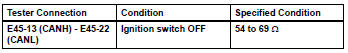

- Check wire harness (center airbag sensor assembly - battery and body ground)
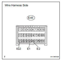
- Disconnect the e45 center airbag sensor connector.
- Measure the resistance of the wire harness side connector.
Standard resistance 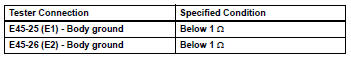
- Measure the voltage of the wire harness side connector.
Standard resistance 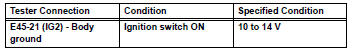

Replace center airbag sensor assembly
 Combination meter ecu communication stop mode
Description
Wiring diagram
Inspection procedure
Notice:
Turn the ignition switch off before measuring the resistances of the
main wire and the branch
wire.
After the ignition swi ...
 4Wd control ecu communication stop mode
Description
Hint:
For vehicle with 4wd only.
Wiring diagram
Inspection procedure
Notice:
Turn the ignition switch off before measuring the resistances of the
main wire and the bra ...
Other materials:
Compressor solenoid circuit (2006/01- )
Description
In this circuit, the compressor receives a refrigerant compression demand
signal from the air conditioning
amplifier. Based on this signal, the compressor changes the degree of
refrigerant compression.
Hint:
*: Compressor and pulley for 2az-fe, compressor and magnetic clu ...
Closing the fuel tank cap
After refueling, turn the fuel tank
cap until you hear a click. Once
the cap is released, it will turn
slightly in the opposite direction.
Caution
When replacing the fuel tank cap
Do not use anything but a genuine toyota fuel tank cap designed for
your
vehicle. Doing so may cause a fire ...
Auto lsd indicator light remains on
Description
This is the auto lsd switch for 2wd. When the auto lsd switch is pushed on,
the auto lsd function is
available and the auto lsd indicator light illuminates.
Hint:
The auto lsd does not operate even if the auto lsd switch is pressed under
the following conditions:
The trc or v ...
