Toyota RAV4 (XA40) 2013-2018 Service Manual: Door lock position circuit
Description
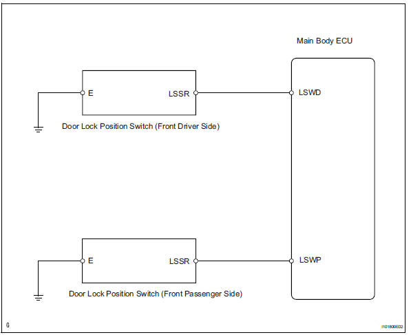
This circuit detects the state of the door lock detection sensor and sends it to the main body ecu.
Wiring diagram
Inspection procedure
- Read value of intelligent tester (door lock position)
- Connect the intelligent tester (with can vim) to the dlc3.
- Turn the ignition switch to the on position and press the intelligent tester main switch on.
- Select the items below in the data list, and read the displays on the intelligent tester.
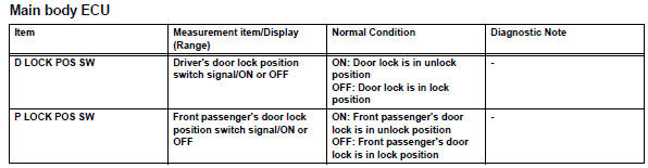
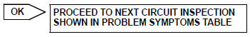
Ok: condition sign can be displayed.

- Inspect front door lock
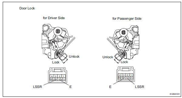
- Remove the front door lock (driver side or passenger side).
- Measure the resistance of the door lock.
Standard resistance:
front door lock (for driver side) 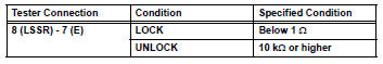
Front door lock (for passenger side)
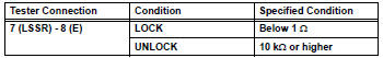

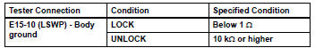
- Check wire harness (main body ecu - door lock and body ground)
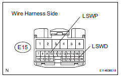
- Disconnect the e15 main body ecu connector.
- Measure the resistance of the wire harness side connector.
Standard resistance:
front door lock (for driver side) 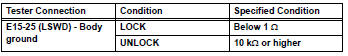
Front door lock (for passenger side)

Replace instrument panel junction block (main body ecu)
 Door courtesy switch circuit
Description
The main body ecu detects the condition of the door courtesy switch.
Wiring diagram
Inspection procedure
Read value of intelligent tester (door courtesy light switch)
Conn ...
 Footwell light circuit
Description
The main body ecu receives information regarding the door lock position
switch and ignition switch, and
turns on each foot light.
Wiring diagram
Inspection procedure
Perform ...
Other materials:
Active test
Hint:
Performing an active test enables components
including the relays, vsv (vacuum switching valve) and
actuators, to be operated without removing any parts.
The active test can be performed with the intelligent
tester. Performing the active test as the first step of
troubleshooting is one ...
Light bulbs
You may replace the following bulbs by yourself. The difficulty
level of replacement varies depending on the bulb. If necessary
bulb replacement seems difficult to perform, contact your
toyota dealer.
For more information about replacing other light bulbs, contact
your toyota dealer.
Prepari ...
How to proceed with troubleshooting
Hint:
Use these procedures to troubleshoot the lighting system.
*: Use the intelligent tester.
Vehicle brought to workshop
Inspect battery voltage
Standard voltage:
11 to 14 v
If the voltage is below 11 v, recharge or replace the battery
before proceeding.
Refer to pr ...
