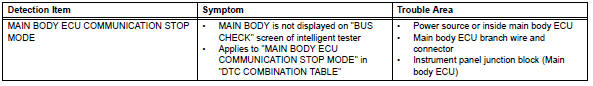
Toyota RAV4 (XA40) 2013-2018 Service Manual: Main body ecu communication stop mode
Description
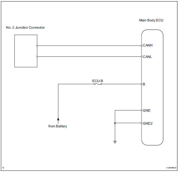
Wiring diagram
Inspection procedure
Notice:
- Turn the ignition switch off before measuring the resistances of the main wire and the branch wire.
- After the ignition switch is turned off, check that the key reminder warning system and light reminder warning system are not in operation.
- Before measuring the resistance, leave the vehicle for at least 1 minute and do not operate the ignition switch, any switches or doors. If doors need to be opened in order to check connectors, open the doors and leave them open.
Hint:
Operating the ignition switch, any switches or any doors triggers related ecu and sensor communication with the can, which causes resistance variation.
- Check can bus line for disconnection (main body ecu branch wire)
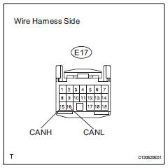
- Disconnect the e17 main body ecu connector.
- Measure the resistance of the wire harness side connector.
Standard resistance 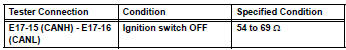

- Check wire harness (main body ecu - battery and body ground)
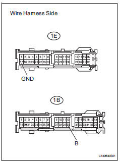
- Disconnect the 1e and 1b junction block connectors.
- Measure the resistance of the wire harness side connector.
Standard resistance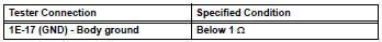
- Measure the voltage of the wire harness side connector.
Standard voltage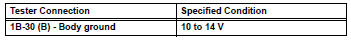

Replace instrument panel junction block (main body ecu)
 Ecm communication stop mode (2006/01- )
Description
Wiring diagram
Inspection procedure
Notice:
Turn the ignition switch off before measuring the resistances of the
main wire and branch
wire.
After the ignition swi ...
 Combination meter ecu communication stop mode
Description
Wiring diagram
Inspection procedure
Notice:
Turn the ignition switch off before measuring the resistances of the
main wire and the branch
wire.
After the ignition swi ...
Other materials:
Engine coolant temperature circuit range / performance problem
Description
Refer to dtc p0115 (see page es-105).
Monitor description
Engine coolant temperature (ect) sensor cold start monitor
When a cold engine start is performed and then the engine is warmed up, if
the ect sensor value does
not change, it is determined that a malfunction has occ ...
Brk relay
On-vehicle inspection
Inspect brk relay
Remove the brk relay from the engine room no. 1
Relay block.
Measure the resistance of the relay.
Standard resistance
If the result is not as specified, replace the relay. ...
Srs warning light remains on
Description
The srs warning light is located on the combination meter.
When the srs is normal, the srs warning light comes on for approximately 6
seconds after the ignition
switch is turned from off to on, and then goes off automatically.
If there is a malfunction in the srs, the srs warni ...
