Toyota RAV4 (XA40) 2013-2018 Service Manual: Cooling system
On-vehicle inspection
- Check cooling system for lea
ks
- Remove the radiator reservoir cap.
Caution:
To avoid the danger of being burned, do not remove the radiator reservoir cap while the engine and radiator are still hot. Thermal expansion will cause hot engine coolant and steam to blow out from the radiator reservoir.
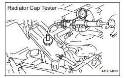
- Fill the radiator and reservoir with coolant, and then attach a radiator cap tester.
- Warm up the engine.
- Pump the radiator cap tester to 118 kpa (1.2 Kgf/
cm2, 17.1 Psi), and then check that the pressure
does not drop.
If the pressure drops, check the hoses, radiator and water pump for leakage.
If there are no signs of external coolant leaks, check the heater core, cylinder block and head.
- Reinstall the radiator reservoir cap.
- Check engine coolant level of reservoir
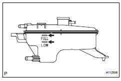
- The engine coolant should be between the low
and full lines when the engine is cold.
If low, check for leakage and add toyota super long life coolant (sllc) or similar high quality ethylene glycol based non-silicate, non-amine, nonnitrite, and non-borate coolant with long-life hybrid organic acid technology up to the full line
- Check engine coolant quality
- Remove the radiator reservoir cap.
Caution:
To avoid the danger of being burned, do not remove the radiator reservoir cap while the engine and radiator are still hot. Thermal expansion will cause hot engine coolant and steam to blow out from the radiator.
- Check for any excessive deposits of rust or scale
around the radiator reservoir cap and radiator filler
hole; the coolant should be free of oil.
If excessively dirty, replace the coolant.
- Install the radiator reservoir cap.
 Battery current sensor
On-vehicle inspection
Check battery current sensor assembly
Measure the resistance of the sensor.
Standard resistance
If the result is not as specified, replace the sensor
assembly.
...
 Cooling fan system
Parts location
System diagram
On-vehicle inspection
Hint:
It is normal for the cooling fan to sometimes rotate when the
ignition switch is turned from acc to on.
Check cooling fan ope ...
Other materials:
Summary of the blind spot monitor
The blind spot monitor is a system that has 2 functions;
The blind spot monitor function
Assists the driver in making the decision when changing lanes
The rear cross traffic alert function
Assists the driver when backing up
These functions use same sensors.
Bsm main switch
...
Disassembly
Fix differential carrier sub-assembly
Fix the rear differential carrier in place with the
overhaul attachment.
Remove stud bolt
Remove the 4 stud bolts from the transmission
coupling.
Remove differential drain plug
Using a 10 mm socket hexagon wrench, remove ...
Differential case
Components
Disassembly
Remove front differential ring gear
Place the matchmarks on the ring gear and
differential case.
Remove the 14 bolts.
Using a plastic-faced hammer, tap on the ring gear
to remove it from the case.
Remove front differential case ...
