Toyota RAV4 (XA40) 2013-2018 Service Manual: Compressor and pulley (for 2gr-fe)
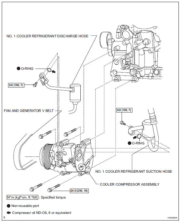
Components
Removal
- Discharge refrigerant from refrigeration system (see page ac-172)
- Disconnect cable from negative battery terminal
Caution:
Wait at least 90 seconds after disconnecting the cable from the negative (-) battery terminal to prevent airbag and seat belt pretensioner activation.
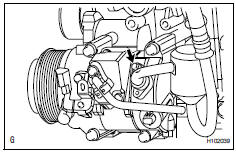
- Disconnect no. 1 Cooler refrigerant suction hose
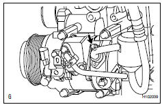
- Remove the bolt and disconnect the cooler refrigerant suction hose from the cooler compressor.
- Remove the o-ring from the cooler refrigerant suction hose.
Notice:
Seal the openings of the disconnected parts using vinyl tape to prevent moisture and foreign matter from entering them.
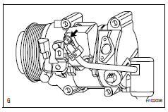
- Disconnect no. 1 Cooler refrigerant discharge hose
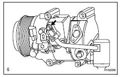
- Remove the bolt and disconnect the cooler refrigerant discharge hose from the cooler compressor.
- Remove the o-ring from the cooler refrigerant discharge hose.
Notice:
Seal the openings of the disconnected parts using vinyl tape to prevent moisture and foreign matter from entering them.
- Remove fan and generator v belt (see page em-8)
- Remove cooler compressor assembly
- Disconnect the connector.
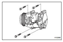
- Remove the 4 bolts and cooler compressor.
Installation
- Install cooler compressor assembly
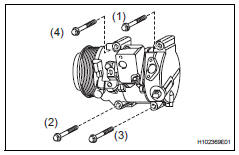
- Install the cooler compressor with the 4 bolts.
Torque: 24.5 N*m (250 kgf*cm, 18 ft.*Lbf)
Notice:
Tighten the bolts in the order shown in the illustration to install the cooler compressor.
- Connect the connector.
- Connect no. 1 Cooler refrigerant discharge hose
- Remove the attached vinyl tape from the hose.
- Sufficiently apply compressor oil to a new o-ring and the fitting surface of the cooler compressor.
Compressor oil: nd-oil 8 or equivalent
- Install the o-ring to the cooler refrigerant discharge hose.
- Connect the cooler refrigerant discharge hose to the cooler compressor with the bolt.
Torque: 9.8 N*m (100 kgf*cm, 7 ft.*Lbf)
- Connect no. 1 Cooler refrigerant suction hose
- Remove the attached vinyl tape from the hose.
- Sufficiently apply compressor oil to a new o-ring and the fitting surface of the cooler compressor.
Compressor oil: nd-oil 8 or equivalent
- Install the o-ring to the cooler refrigerant suction hose.
- Connect the cooler refrigerant suction hose to the cooler compressor with the bolt.
Torque: 9.8 N*m (100 kgf*cm, 7 ft.*Lbf)
- Install fan and generator v belt (see page em-8)
- Connect cable to negative battery terminal
- Charge refrigerant (see page ac-172)
- Warm up engine (see page ac-173)
- Check for leakage of refrigerant (see page ac-173)
 Compressor and pulley (for 2az-fe)
Components
Removal
Discharge refrigerant from
refrigeration system (see page ac-172)
Disconnect cable from negative battery
terminal
Caution:
Wait at least 90 seconds after disconne ...
 Condenser
Components
On-vehicle inspection
Inspect cooler condenser assembly
If the fins of the cooler condenser are dirty, clean
them with water. Dry the fins with compressed air.
Notic ...
Other materials:
Abs and traction actuator (skid control ecu) communication stop mode
Description
Wiring diagram
Inspection procedure
Notice:
Turn the ignition switch off before measuring the resistances
of the main wire and the branch
wire.
After the ignition switch is turned off, check that the key
reminder warning system and light
reminder warning system ...
Installation
Hint:
Use the same procedures for the lh side and rh side.
The procedures listed below are for the lh side.
Install speed sensor front lh
Notice:
To prevent interference with other parts, do not twist
the sensor wire's painted line areas when installing
it.
Set the sensor body ...
Monitor drive pattern
Test monitor drive pattern for ect
Caution:
Perform this drive pattern on a level surface and
strictly observe the posted speed limits and traffic
laws while driving.
Hint:
Performing this drive pattern is one method to simulate
the ect's malfunction detection conditions.
The dtcs may ...
