Toyota RAV4 (XA40) 2013-2018 Service Manual: Center airbag sensor assembly communication circuit malfunction

Description
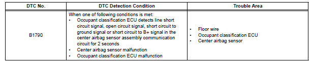
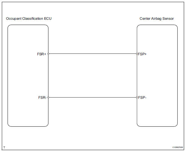
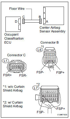
The center airbag sensor communication circuit consists of the occupant classification ecu and the center airbag sensor.
Dtc b1790 is recorded when a malfunction is detected in the center airbag sensor communication circuit.
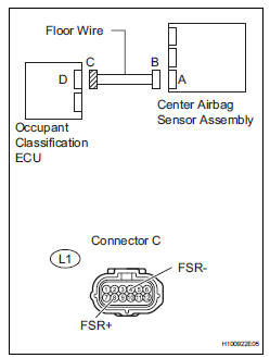
Wiring diagram
Inspection procedure
Hint:
- If troubleshooting (wire harness inspection) is difficult to perform, remove the front passenger seat installation bolts to see the undersurface of the seat cushion.
- In the above case, hold the seat so that it does not tip over. Holding the seat for a long period of time may cause a problem, such as seat rail deformation. Hold the seat up only for as long as necessary.
- Check for dtc
- Turn the ignition switch on.
- Clear the dtcs (see page rs-249).
Hint:
First clear dtcs stored in the occupant classification ecu and then in the center airbag sensor.
- Turn the ignition switch off.
- Turn the ignition switch on.
- Check the dtcs (see page rs-249).
Ok: dtc b1790 is not output.
Hint:
Dtcs other than dtc b1790 may be output at this time, but they are not related to this check.

- Check connection of connector
- Turn the ignition switch off.
- Disconnect the cable from the negative (-) battery terminal, and wait for at least 90 seconds.
- Check that the connectors are properly connected to the occupant classification ecu and the center airbag sensor.
Ok: the connectors are properly connected.

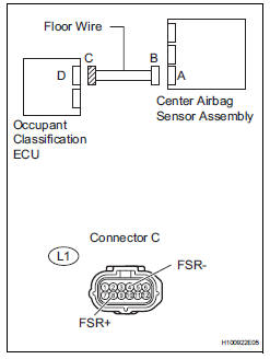
- Check floor wire (to b+)
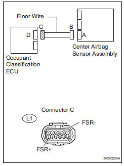
- Disconnect the connectors from the occupant classification ecu and the center airbag sensor.
- Connect the cable to the negative (-) battery terminal, and wait for at least 2 seconds.
- Turn the ignition switch on.
- Measure the voltage of the wire harness side connector.
Standard voltage 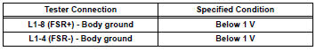

- Check floor wire (for open)
- Turn the ignition switch off.
- Disconnect the cable from the negative (-) battery terminal, and wait for at least 90 seconds.
- Using a service wire, connect terminals l6-12 (fsp+) *1 and l6-13 (fsp-) *1 or l7-16 (fsp+) *2 and l7-24 (fsp-) *2 of connector b.
Notice:
Do not forcibly insert a service wire into the terminals of the connector when connecting them.
- Measure the resistance of the wire harness side connector.
Standard resistance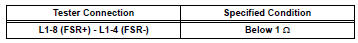
Hint:
*1: W/o curtain shield airbag
*2: W/ curtain shield airbag


- Check floor wire (for short)
- Disconnect the service wire from connector b.
- Measure the resistance of the wire harness side connector.
Standard resistance 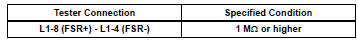

- Check floor wire (to ground)
- Measure the resistance of the wire harness side connector.
Standard resistance 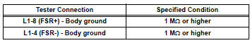

- Check for dtc
- Connect the connectors to the occupant classification ecu and the center airbag sensor.
- Connect the cable to the negative (-) battery terminal, and wait for at least 2 seconds.
- Turn the ignition switch on.
- Clear the dtcs (see page rs-249).
Hint
First clear dtcs stored in the occupant classification ecu and then in the center airbag sensor.
- Turn the ignition switch off.
- Turn the ignition switch on.
- Check the dtcs (see page rs-249).
Ok: dtc b1790 is not output.
Hint:
Dtcs other than dtc b1790 may be output at this time, but they are not related to this check.

- Replace occupant classification ecu
- Turn the ignition switch off.
- Disconnect the cable from the negative (-) battery terminal, and wait for at least 90 seconds.
- Replace the occupant classification ecu (see page rs- 392).
Hint:
Perform the inspection using parts from a normal vehicle if possible.

- Perform zero point calibration
- Connect the cable to the negative (-) battery terminal, and wait for at least 2 seconds.
- Connect the intelligent tester (with can vim) to the dlc3.
- Turn the ignition switch on.
- Using the intelligent tester, perform the zero point calibration (see page rs-241).
Ok: completed is displayed.

- Perform sensitivity check
- Using the intelligent tester, perform the sensitivity check (see page rs-241).
Standard value: 27 to 33 kg (59.52 To 72.75 Lb)

- Check for dtc
- Turn the ignition switch on.
- Clear the dtcs (see page rs-249).
Hint:
First clear dtcs stored in the occupant classification ecu and then in the center airbag sensor.
- Turn the ignition switch off.
- Turn the ignition switch on.
- Check the dtcs (see page rs-249).
Ok: dtc b1790 is not output.
Hint:
Dtcs other than dtc b1790 may be output at this time, but they are not related to this check.

End
 Rear occupant classification sensor rh collision detection
Description
Dtc b1788 is output when the occupant classification ecu receives a collision
detection signal sent by
the rear occupant classification sensor rh when an accident occurs.
Dtc b1 ...
 Occupant classification sensor power supply circuit malfunction
Description
The occupant classification sensor power supply circuit consists of the
occupant classification ecu and
the occupant classification sensors.
Dtc b1793 is recorded when a malfunc ...
Other materials:
Removal
Remove radiator grille sub-assembly
Remove the 4 bolts and 4 nuts.
Detach the 6 claws and remove the radiator grille.
Remove no. 1 Radiator grille lower
Detach the 16 claws and remove the radiator grille.
Remove no. 2 Radiator grille lower
Detac ...
For vehicles with supplemental restraint system
The rav4 is equipped with a supplemental restraint
system (srs). The srs of this vehicle consists of the
following:
Steering pad
Front passenger airbag assembly
Front seat side airbag assembly
Front seat outer belt assembly with pretensioner
Curtain shield
Center airbag sensor
Fron ...
Valve clearance
Adjustment
Disconnect cable from negative battery
terminal
Caution:
Wait at least 90 seconds after disconnecting the
cable from the negative (-) battery terminal to
prevent airbag and seat belt pretensioner activation.
Remove front wheel rh
Remove no. 1 Engine under cover
Remove ...
