Toyota RAV4 (XA40) 2013-2018 Service Manual: Disassembly (2005/11-2006/01)
- Remove front axle inboard joint boot no. 2 Clamp lh
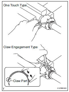
- One touch type:
- Using a screwdriver, remove the inboard joint boot clamp, as shown in the illustration.
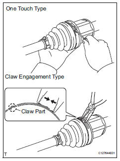
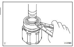
- Claw engagement type:
- Using needle-nose pliers, remove the inboard joint boot clamp, as shown in the illustration.
- Remove front axle inboard joint boot no. 2 Clamp rh
Hint:
Use the same procedures described for the lh side.
- Remove front axle inboard joint boot clamp lh
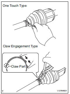
- One touch type:
- Using a screwdriver, remove the inboard joint boot clamp, as shown in the illustration.
- Claw engagement type:
Using needle-nose pliers, remove the inboard joint boot clamp, as shown in the illustration.
- Remove front axle inboard joint boot clamp rh
Hint:
Use the same procedures described for the lh side.
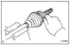
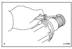
- Remove front axle inboard joint boot
- Remove the boot from the inboard joint.
- Remove front drive inboard joint assembly lh
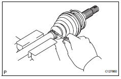
- Remove any old grease from the inboard joint.
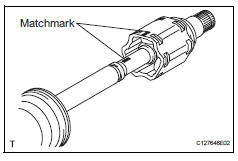
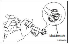
- Put matchmarks on the inboard joint and outboard joint shaft.
Notice:
Do not punch the marks.
- Remove the inboard joint from the outboard joint shaft.
- Using a snap ring expander, remove the shaft snap ring.
- Put matchmarks on the outboard joint shaft and tripod joint.
Notice:
Do not punch the marks.
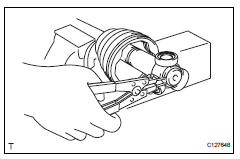
- Using a brass bar and hammer, tap out the tripod joint from the outboard joint shaft.
Notice:
Do not tap the rollers.
- Remove the inboard joint boot.
- Remove front drive shaft damper clamp lh
- One touch type:
- Using a screwdriver, remove the drive shaft damper clamp, as shown in the illustration.
- Claw engagement type:
Using needle-nose pliers, remove the drive shaft damper clamp, as shown in the illustration.
- Remove front drive shaft damper lh
- Remove the front drive shaft damper from the outboard joint shaft.
- Remove front axle outboard joint boot no. 2 Clamp lh
- Using a screwdriver, remove the outboard joint boot clamp, as shown in the illustration.
- Remove front axle outboard joint boot clamp lh
- Using a screwdriver, remove the outboard joint boot clamp, as shown in the illustration.
- Remove front axle outboard joint boot
- Remove the outboard joint boot from the outboard joint shaft.
- Remove any old grease from the outboard joint.
- Remove front drive shaft hole snap ring lh
- Using a screwdriver, remove the hole snap ring.
- Remove front drive shaft dust cover lh
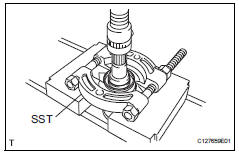
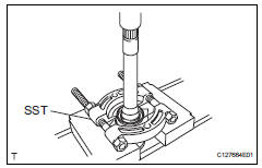
- Using sst and a press, press out the shaft dust cover
Sst 09950-00020
Notice:
Be careful not to drop the inboard joint
- Remove front drive shaft dust cover rh
Hint:
Use the same procedures described for the lh side.
- Remove drive shaft bearing case
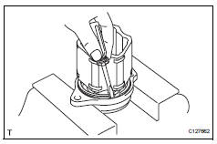
- Using a screwdriver, remove the bearing case snap ring.
- Using a press, press out the drive shaft bearing case.
Hint:
Be careful not to drop the inboard joint
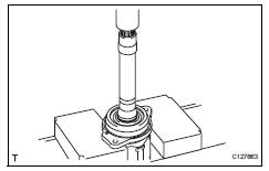
- Remove front drive shaft dust cover
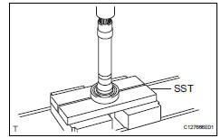
- Using sst and a press, press out the drive shaft dust cover.
Sst 09950-00020
Hint:
Be careful not to drop the inboard joint
- Remove front drive shaft bearing
- Using a snap ring expander, remove the snap ring.
- Using sst and a press, press out the drive shaft bearing.
Sst 09527-10011
- Remove the snap ring.
 Removal
(2006/01- )
Removal
(2006/01- )
Remove front wheel
Drain automatic transaxle fluid
Drain the automatic transaxle fluid for u140f (see
page ax-147).
Drain the automatic transaxle fluid for u241e (see
page ax-146).
...
 Disassembly (2006/01- )
Remove front axle inboard joint boot no. 2 Clamp
One touch type:
using a screwdriver, remove the inboard joint boot
clamp, as shown in the illustration.
Claw engagement type:
usin ...
Other materials:
Voice settings
This screen is used for setting the voice command guidance
system.
Adjust the voice guidance volume
setting.
Set the voice recognition
prompts ŌĆ£highŌĆØ, ŌĆ£lowŌĆØ or ŌĆ£offŌĆØ.
Train voice recognition
Set the voice prompt interrupt
on/off.
Voice recognition tutorial
To re ...
Headlight dimmer switch
Precaution
Precaution for vehicle with srs
Some procedures in this section may affect the
supplemental restraint system (srs). Prior to
performing the procedures, read the srs section's
"precaution" (see page rs-1).
Components
Removal
Disconnect cable from negat ...
Air-fuel ratio (a/f) and heated oxygen (ho2) sensor
monitors (active air-fuel ratio control type)
Preconditions
The monitor will not run unless:
2 Minutes or more have elapsed since the engine
was started.
The engine coolant temperature (ect) is 75┬░c
(167┬░f) or more.
Cumulative driving time at a vehicle speed of 48
km/h (30 mph) or more exceeds 6 minutes.
Air-fuel rat ...
