Toyota RAV4 (XA40) 2013-2018 Service Manual: Disassembly (2006/01- )
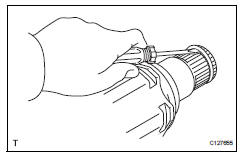
- Remove front axle inboard joint boot no. 2 Clamp
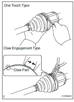
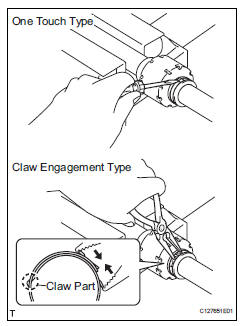
- One touch type: using a screwdriver, remove the inboard joint boot clamp, as shown in the illustration.
- Claw engagement type: using needle-nose pliers, remove the inboard joint boot clamp, as shown in the illustration.
- Remove front axle inboard joint boot clamp
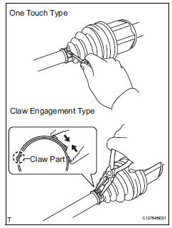
- One touch type: using a screwdriver, remove the inboard joint boot clamp, as shown in the illustration.
- Claw engagement type: using needle-nose pliers, remove the inboard joint boot clamp, as shown in the illustration.
- Remove front axle inboard joint boot
- Remove the boot from the inboard joint.
- Remove front drive inboard joint assembly lh
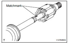
- Remove any old grease from the inboard joint.
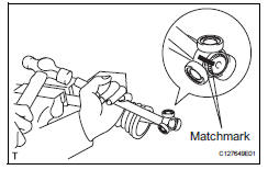
- Put matchmarks on the inboard joint and outboard joint shaft.
Notice:
Do not punch the marks.
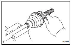
- Remove the inboard joint from the outboard joint shaft.
- Using a snap ring expander, remove the shaft snap ring.
- Put matchmarks on the outboard joint shaft and tripod joint.
Notice:
Do not punch the marks.
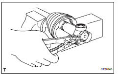
- Using a brass bar and hammer, tap out the tripod joint from the outboard joint shaft.
Notice:
Do not tap the rollers.
- Remove the inboard joint boot.
- Remove front drive inboard joint assembly rh
Hint:
Use the same procedures described for the lh side.
- Remove front drive shaft damper clamp lh
- One touch type: using a screwdriver, remove the drive shaft damper clamp, as shown in the illustration.
- Claw engagement type: using needle-nose pliers, remove the drive shaft damper clamp, as shown in the illustration.
- Remove front drive shaft damper lh
- Remove the front drive shaft damper from the outboard joint shaft.
- Remove front axle outboard joint boot no. 2 Clamp
- Using a screwdriver, remove the outboard joint boot clamp, as shown in the illustration.
- Remove front axle outboard joint boot clamp
- Using a screwdriver, remove the outboard joint boot clamp, as shown in the illustration.
- Remove front axle outboard joint boot
- Remove the outboard joint boot from the outboard joint shaft.
- Remove any old grease from the outboard joint.
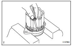
- Remove front drive shaft hole snap ring lh
- Using a screwdriver, remove the hole snap ring.
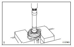
- Remove front drive shaft dust cover lh
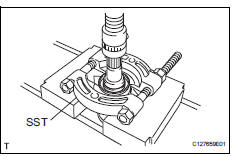
- Using sst and a press, press out the shaft dust cover.
Sst 09950-00020
Notice:
Be careful not to drop the inboard joint.
- Remove front drive shaft dust cover rh
Hint:
Use the same procedures described for the lh side.
- Remove drive shaft bearing case (for rh)
- Using a screwdriver, remove the bearing case snap ring.
- Using a press, press out the drive shaft bearing case.
Hint:
Be careful not to drop the inboard joint.
- Remove front drive shaft dust cover (for rh)
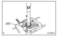
- Using sst and a press, press out the drive shaft dust cover.
Sst 09950-00020
Notice:
Be careful not to drop the inboard joint.
- Remove front drive shaft bearing
- Using a snap ring expander, remove the snap ring.
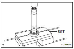
- Using sst and a press, press out the drive shaft bearing.
Sst 09527-10011
- Remove the bearing case snap ring.
 Disassembly (2005/11-2006/01)
Remove front axle inboard joint boot no. 2 Clamp lh
One touch type:
Using a screwdriver, remove the inboard joint
boot clamp, as shown in the illustration.
Claw engagement t ...
 Reassembly (2005/11-2006/01)
Install drive shaft bearing case subassembly
Using sst and a press, press in the drive shaft
bearing case to the inboard joint rh.
Sst 09527-10011, 09710-04081
Notice:
The bearing ...
Other materials:
Disposal
Hint:
When scrapping a vehicle equipped with an srs or disposing
of the steering pad, be sure to deploy the airbag first in
accordance with the procedure described below. If any
abnormality occurs with the airbag deployment, contact the
service dept. Of toyota motor sales, u.S.A., Inc.
Caution ...
Check for intermittent problems
Hint:
Inspect the vehicle's ecm using check mode. Intermittent
problems are easier to detect with the intelligent tester when
the ecm is in check mode. In check mode, the ecm uses 1
trip detection logic, which is more sensitive to malfunctions
than normal mode (default), which uses 2 trip detec ...
Trailer towing
Your vehicle is designed primarily as a passenger-and-load-carrying
vehicle. Towing a trailer can have an adverse impact on
handling, performance, braking, durability, and fuel consumption.
For your safety and the safety of others, you must not overload
your vehicle or trailer. You must also e ...
