Toyota RAV4 (XA40) 2013-2018 Service Manual: Front suspension lower no. 1 Arm
Components
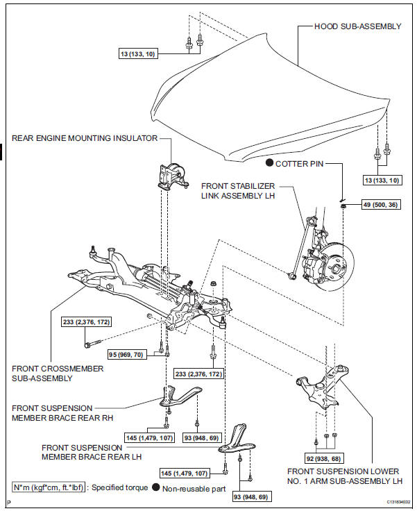
Removal
- Remove front wheel
- Remove hood sub-assembly
- Remove the hood (see page ed-4).
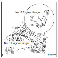
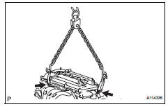
- Suspend engine assembly
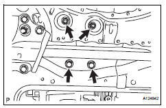
- Install the no. 1 And no. 2 Engine hangers with the bolts as shown in the illustration.
Torque: 38 n*m (387 kgf*cm, 28 ft.*Lbf)
parts no. 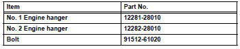
- Attach the sling device and the engine with the chain block.
- Disconnect front stabilizer link assembly lh (see page sp-30)
- Disconnect front stabilizer link assembly rh
- Use the same procedure described for the lh side.
- Disconnect front suspension lower no. 1 Arm sub-assembly lh
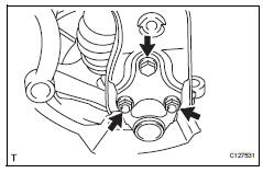
- Remove the 2 nuts and bolt, and disconnect the lower arm from the ball joint.
- Disconnect front suspension lower no. 1 Arm sub-assembly rh
Hint:
Use the same procedures described for the lh side.
- Disconnect front crossmember subassembly
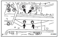
- Remove the 2 nuts, 2 bolts and engine mounting insulator rear.
- Remove the bolt from the suspension member.
- Support the crossmember with the jack.
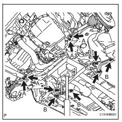
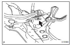
- Remove the bolts labeled a.
- Remove the 4 bolts from the member reinforcement.
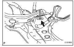
- Remove the bolts labeled b.
- Remove the 6 bolts from the member brace.
- Slowly lower the jack, and disconnect the crossmember from the vehicle.
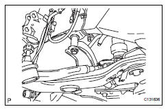
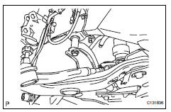
- Remove front suspension lower no. 1 Arm sub-assembly lh
- Remove the bolt and nut from the suspension member (front side).
- Remove the bolt and nut from the suspension member (rear side). Then remove the lower arm.
- Remove front suspension lower no. 1 Arm sub-assembly rh
Hint:
Use the same procedures described for the lh side.
Installation
- Temporarily install front suspension lower no. 1 Arm lh
- Temporarily install the lower arm with the bolt and nut to the front side.
- Temporarily install the lower arm with the bolt and nut to the rear side.
- Temporarily install front suspension no. 1 Lower arm sub-assembly rh
Hint:
Use the same procedures described for the lh side.
- Connect front crossmember subassembly
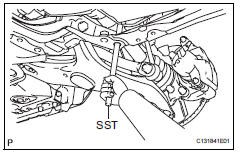
- Slowly raise the crossmember jack, and connect the crossmember to the body.
- Using sst, align the holes of the suspension member and body.
Sst 09670-00020
- Perform the procedure above on the other side.
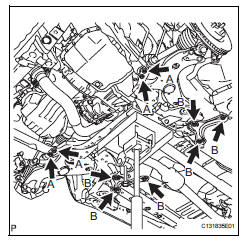
- Install the member reinforcement with the 4 bolts labeled a.
- Install the suspension member brace with the 6 bolts labeled b.
- Install the suspension member with the bolt to the body.
- Perform the procedure above on the other side.
- Install the engine mounting insulator rear with the 2 nuts and 2 bolts.
- Install front stabilizer link assembly lh (see page sp-30)
- Connect front suspension lower no. 1 Arm sub-assembly lh
- Connect the lower arm with the 2 bolts and nut to the ball joint.
Torque: 92 n*m (938 kgf*cm, 68 ft.*Lbf)
- Install front wheel
Torque: 103 n*m (1,050 kgf*cm, 76 ft.*Lbf)
- Stabilize suspension (see page sp-12)
- Tighten front cross member sub-assembly
- Tighten the bolts and nuts.
Torque: 87 n*m (887 kgf*cm, 64 ft.*Lbf) for bolt a
93 N*m (948 kgf*cm, 69 ft.*Lbf) for bolt b
145 N*m (1,479 kgf*cm, 107 ft.*Lbf) for body
95 N*m (969 kgf*cm, 70 ft.*Lbf) for engine mounting insulator
- Tighten front suspension lower no. 1 Arm sub-assembly lh
- Using sst, and tighten the bolt on the front side.
Sst 09961-01270
Torque: 223 n*m (2,376 kgf*cm, 172 ft.*Lbf) for use without sst
175 N*m (1,785 kgf*cm, 129 ft.*Lbf) for use with sst
Notice:
Do not tighten the nut.
- Fix the nut in place and tighten the bolt on the rear side.
Torque: 223 n*m (2,376 kgf*cm, 172 ft.*Lbf)
Notice:
Do not tighten the nut.
- Tighten front suspension lower no. 1 Arm sub-assembly rh
Hint:
Use the same procedures described for the lh side.
- Install hood sub-assembly (see page ed-7)
- Inspect and adjust hood sub-assembly
- Inspect and adjust the hood (see page ed-5).
- Inspect and adjust front wheel alignment
- Inspect and adjust the front wheel alignment (see page sp-3).
 Suspension & axle front shock absorber with coil spring (for sport package)
Components
Removal
Hint:
Use the same procedures for the rh side and lh side.
The procedures listed below are for the lh side.
Remove front wheel
Remove front speed sensor lh (see ...
 Front lower ball joint
Components
Removal
Hint:
Use the same procedures for the rh side and lh side.
The procedures listed below are for the lh side.
Remove front wheel
Remove front speed sensor lh (for ...
Other materials:
General maintenance (2006/01- )
Inspect drive belt (see page em-7)
Replace spark plugs (see page ig-7)
Replace air cleaner filter
Remove the air filter.
Visually check that the air filter is not excessively
damaged or oily.
Replace the air filter with a new one, if necessary.
Replace engine oil and oil fil ...
Fail-safe chart
Fail-safe chart
This function minimizes the loss of the ect functions
when a malfunction occurs in a sensor or solenoid.
Automatic transmission fluid (atf) temperature
sensor:
when the atf temperature sensor has a
malfunction, o/d up-shift is prohibited
Counter gear speed sensor n ...
Installation
Install generator assembly
Confirm that the wire harness of the crankshaft
position sensor is secured to the wire harness
clamp bracket through the back of the rib of the
timing chain cover.
Install the generator with the 2 bolts.
Torque: 21 n*m (215 kgf*cm, 16 ft.*Lb ...
